Creating surfaces from Point Cloud data in InfraWorks - Exercise
Task 1: Begin a new InfraWorks model
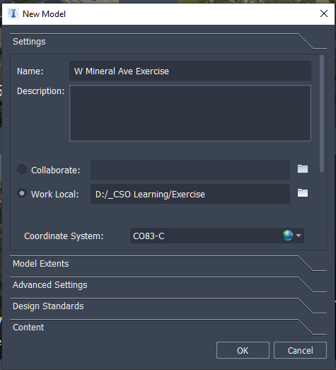
- On the InfraWorks Home screen, click on New.
- Give your model a name. In this example we use the name W Mineral Ave.
- Check on Work Local and select a folder for your model and supporting files.
- Click on the blue globe to set the Coordinate system. Select USA, Colorado from the Category drop-down list, then select CO83-C from the Code list.
- Click OK.
Task 2: Import Point Cloud
- Open the Data Sources pane by clicking on the Data icon.

- On the Data sources pane, drop down the data file source list and click on Point Cloud.
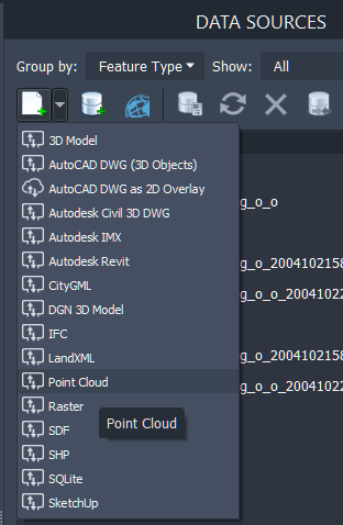
- Browse to your location of the data set and select Intersection and Parking.rcs.
- After it has imported, right-click on the data file name and select Configure.
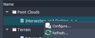
- Click Close and Refresh on the Data Source Configuration dialog box.
- The temporary ground terrain will appear as a shaded rectangle at elevation 0. Carefully zoom out to find the point cloud which will be located very high above the ground terrain at elevation 1650.
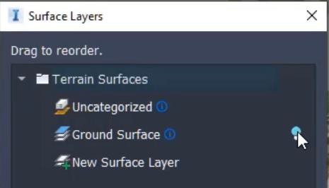
- When you have the point cloud displayed in the view, open the Surface Layers by clicking on the Layers icon.

- Click on the yellow light bulb to turn off the display of the Ground Surface.
Task 3: Add a view Bookmark
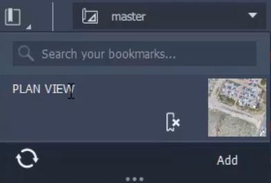
- Click on the Bookmark icon and Add the current view.
- You can name it PLAN VIEW.
Task 4: Process the Point Cloud
- Click on the Point Cloud Terrain icon to launch the Point Cloud Terrain settings box.

- Set the Processing Rules as follows:
- Ground: Optimum
- Linear Feature: Passive
- Vertical Feature: Fewer Features
- Override Model Point Cloud: toggle off
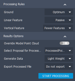
- Click Start Processing.
Task 5: Turn on ground surface layer visibility
- Return to the Surface Layers settings box and turn on the Ground Surface.
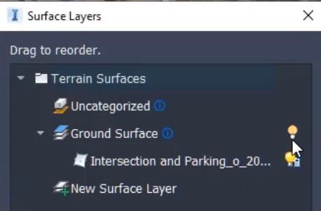
- Click on Apply, then OK.
Task 6: Add a contour view style
- Click on the Display Styles to drop down the list.
- Click on Add to open the View Settings dialog.
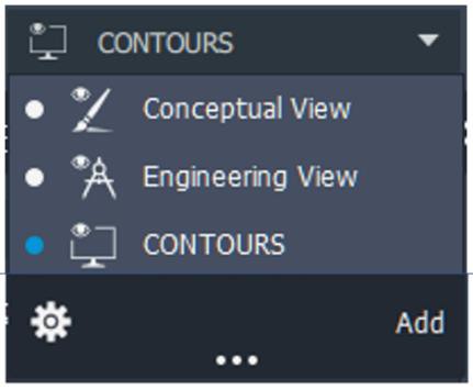
- Experiment with the Visualization settings and the Terrain Settings to make a style that displays contours. Click on the icons at the top of the box to change the settings options. Here are some example settings to try.
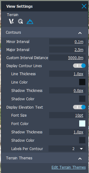
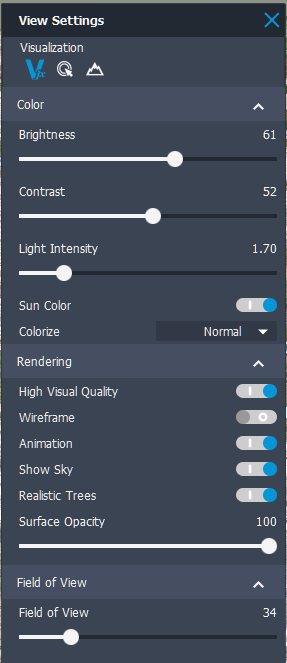
- When you have a good style, name it CONTOURS.
Task 7: Review the ground surface results
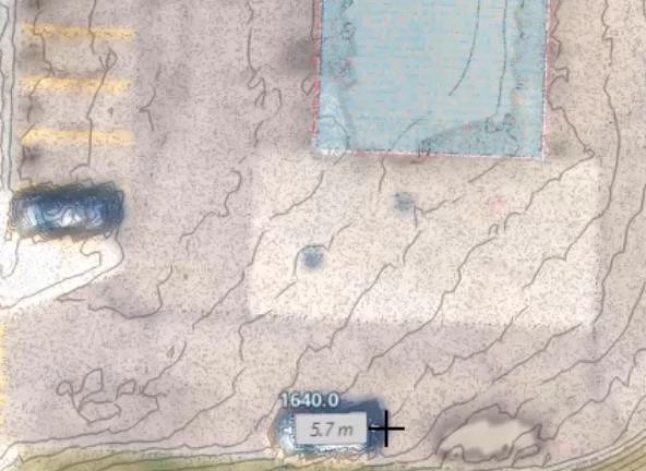
- Navigate the model to see how the surface was generated. With contours displayed you can see if the terrain is represented well of if there are extra details that are distorting the true surface condition. For example, you can see that the parked vehicles are added to the surface.
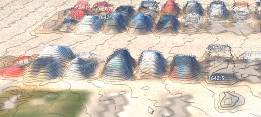
- Navigate to the gas station area.
- Use the Measure icon to select Point to Point Distance.
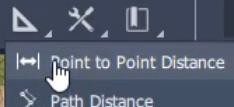
- Measure the distance across one of the parked automobiles. The measurement should be a little more than 5 meters.
Task 8: Process the Point Cloud data with custom processing rule settings
- Return to the PLAN VIEW bookmark.
- Launch the Point Cloud Terrain processing settings box.
- Set the Override Model Point Cloud toggle to off.
- Select Custom for Ground Details and use the following settings. Note you will have to set the Processing Window Size to 40.00 before setting the Ground Details to 5.00.
- Ground Details: 5.00
- Terrain Raster Resolution: 2000
- Fill Terrain Holes: on
- Processing Window Size: 40.00
- Linear Feature: Passive
- Vertical Feature: Fewer Features
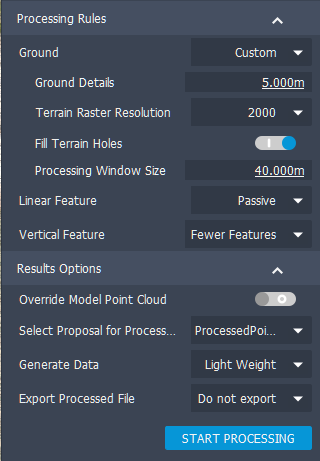
- Click Start Processing.
Task 9: Manage surface layers
- Return to the Surface Layers settings box.
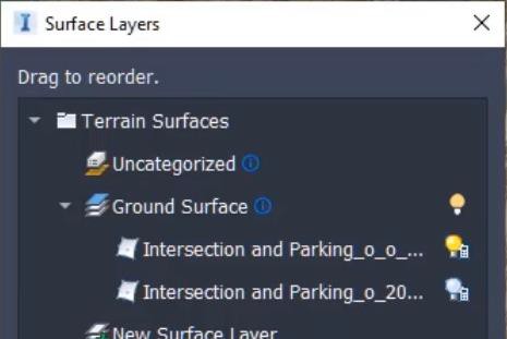
- Click on the surface layer in the Uncategorized collection and drag it into the Ground Surface collection.
- Turn on the visibility of this new layer.
- Turn off the visibility of the previous layer.
- Click on Apply.
Task 10: Review the surface
- Navigate to the parking lot and gas station area of the project and see that the surface is much cleaner and has fewer distortions from automobiles.
- Navigate to the pedestrian bridge area and see if there are voids that have been added.
- Open the Surface Layers settings box and turn on the display of both layers. Click Apply.
- Navigate to the gas station area and position the view to see the automobiles.
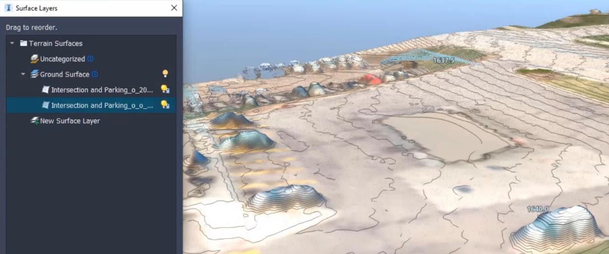
- Move the newest layer to the bottom of the list. Click Apply. Notice that the automobile distortions disappeared.
Task 11: Export the surface
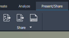
- Click on the IMX Open the Present/Share Menu and click on IMX share.
- Toggle on Use Entire Model.
- Verify that the coordinate system code is CO83-C.
- Designate the folder location for the export.
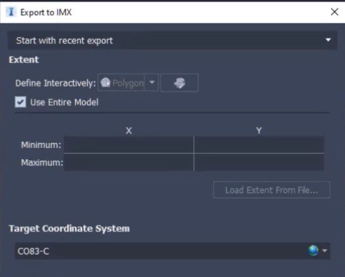
- Click on Export.
Task 12: Import the surface into Civil 3D
- Launch Civil 3D.
- On the Insert Tab, click on InfraWorks and then Open InfraWorks Model.
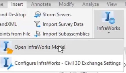
- Browse to and select the IMX file that was just created in InfraWorks.
- Select Please set a coordinate system.
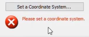
- Select the first option: Use the InfraWorks 360 model coordinate system [CO83-C].
- Click Open Model.
- On the Prospector tab of the Toolspace, expand the Surfaces collection and see the three surface items that were imported. The only one that has data is the AIW_Existing_Ground surface.
You do not need to save this Civil 3D drawing.
Was this information helpful?