00:03
Once you have completed the hydraulic design in InfoDrainage,
00:07
you can export the design and then re-import it back into Civil 3D to complete the design.
00:12
First, in InfoDrainage, be sure the final design is saved.
00:16
Next, in Civil 3D, if you have the original network design still open,
00:21
you must delete it because otherwise, Civil 3D will duplicate it when you import the new design.
00:28
Keep in mind that the goal is to replace the existing design in the surface with the refined hydraulic design you did in InfoDrainage.
00:36
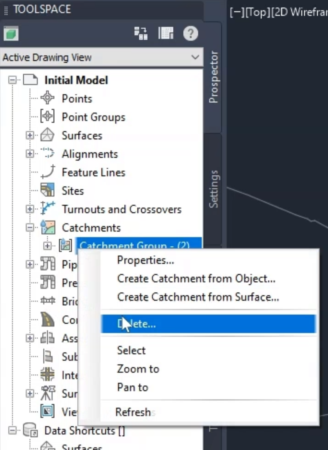
From the Toolspace, Prospector tab, under the Initial model,
00:41
expand the Catchments node,
00:42
Right-click the Catchment Group and select Delete.
00:46
In the confirmation popups, click Yes to confirm the deletion.
00:50
Repeat this for the pipe network.
00:52
In the Toolspace, expand Pipe Networks, and then expand Networks.
00:57
Right-click the Storm01 or named network and select Delete.
01:03
Again, click Yes to the confirmation.
01:06
At this point, you still have the surface showing and the original line showing
01:11
where the pipe network is to be placed when you bring it back in from InfoDrainage.
01:15
On the ribbon, click the Innovyze tab,
01:17
Then, in the Import/Export panel, click Import from InfoDrainage.
01:22
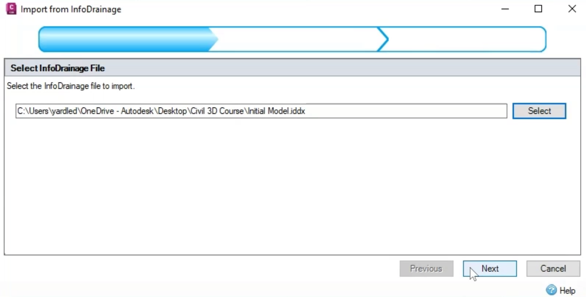
On the first page of the Import from InfoDrainage wizard,
01:26
click Select to browse for and open the new hydraulic design file.
01:31
For this exercise, select Hydraulic Design, and then click Open.
01:36
Back in the wizard, click Next.
01:39
On the Select Phases and Surfaces page, enable the Phases node to include it and the Storm01 surface in the import.
01:47
Expand the drop-down.
01:49
From here, you could also choose to use an existing Civil 3D surface or create a new surface.
01:55
For this exercise, keep Use an existing Civil 3D surface selected, and then click Next.
02:03
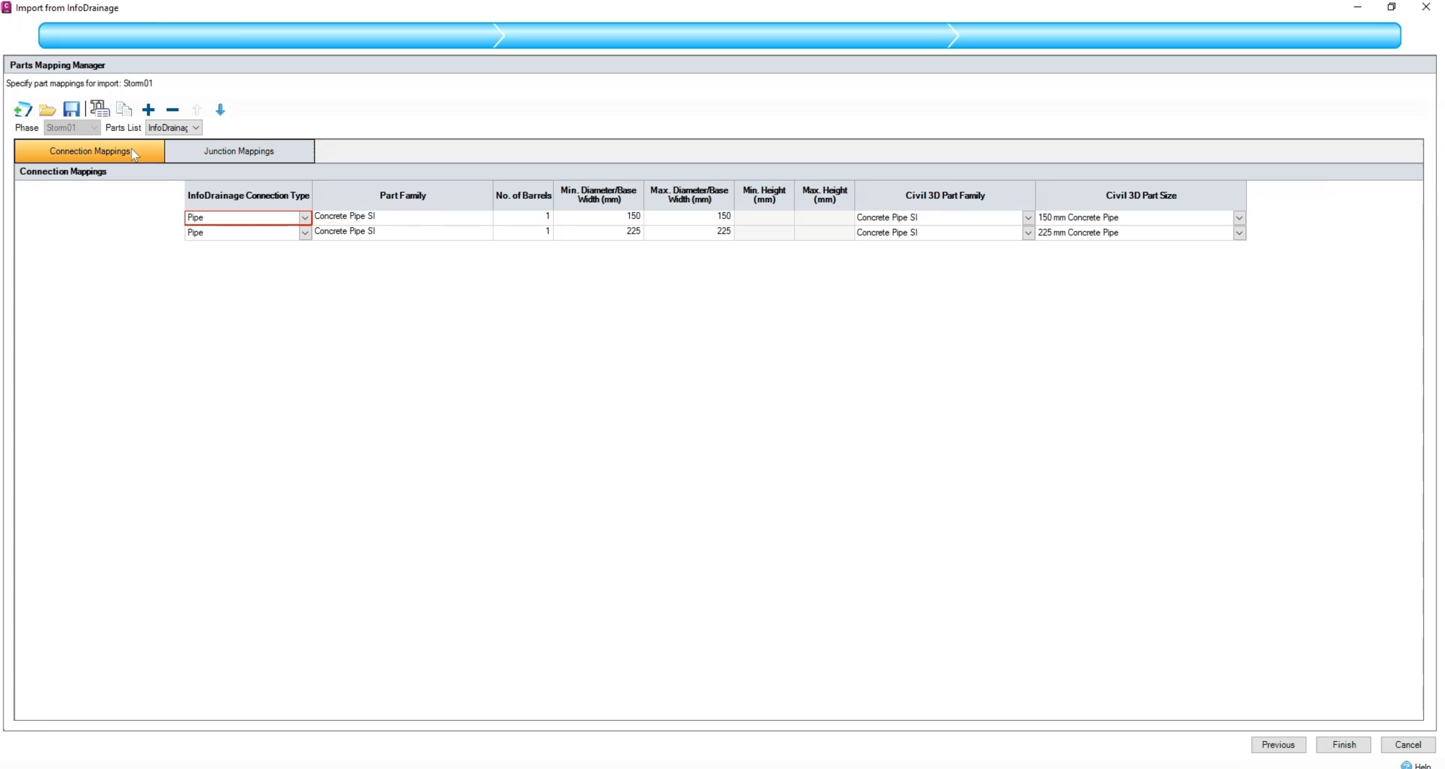
Here, in the Parts Mapping Manager, you match up the InfoDrainage connection and junction types with those in Civil 3D.
02:10
Since a parts list has already been defined earlier in this example,
02:14
the Civil 3D part family and part sizes are already mapped.
02:18
However, if the parts list had not previously been defined,
02:22
you could expand the drop-downs and do that here.
02:25
On the Connection Mappings tab, you can see the two pipe types that are being used for the design,
02:30
and when you click the Junction Mappings tab, you can see the one manhole part as well.
02:35
Be aware that once you have set up these mappings once,
02:38
you can then save them as an InfoDrainage-specific file by clicking Save in the toolbar here.
02:44
This can save you a great deal of time if you are sending the hydraulic design file back and forth between the two programs.
02:51
You can continue to map additional parts and save them throughout the design process.
02:57
To access your saved files, you would click the Open file icon in the toolbar.
03:02
For now, just click Finish.
03:05
The catchments, manholes, and pipes appear back on the surface as the revised network.
03:10
To verify that this is indeed updated data, you can create an alignment.
03:16
From the Toolspace, Prospector tab, expand the Networks node,
03:20
and then right click Storm01 and click Select to select the entire network.
03:26
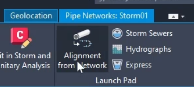
The Pipe Networks Storm01 contextual tab appears on the ribbon.
03:30
In the Launch Pad panel, click Alignment from Network.
03:34
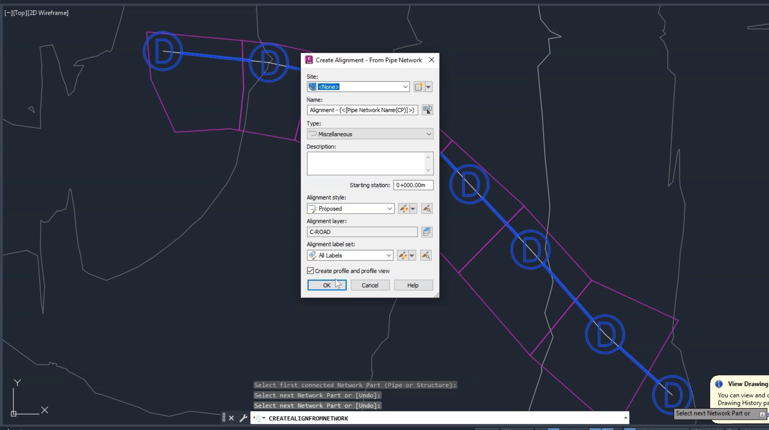
Then in the drawing, pick the first and last manholes in the series.
03:39
Right-click to end the series creation, and the Create Alignment – From Pipe Network dialog box opens.
03:46
For this exercise, accept the defaults and click OK.
03:49
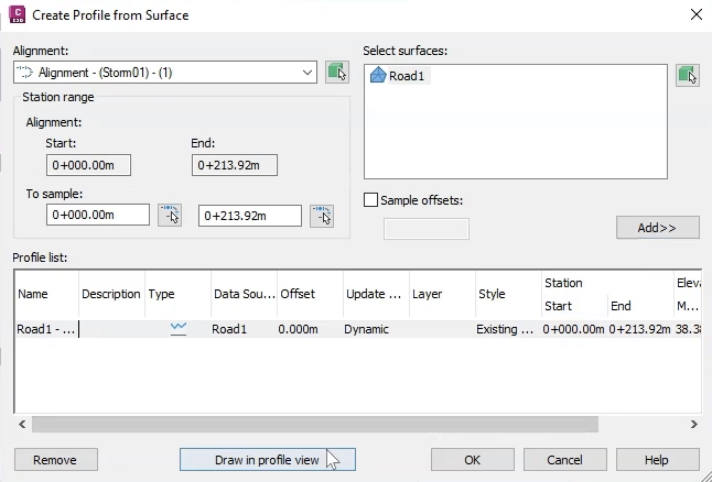
The Create Profile from Surface dialog appears.
03:53
To load the relevant surface, click Add.
03:57
The Road1 surface appears in the Profile list table.
04:01
Click Draw in profile view.
04:04
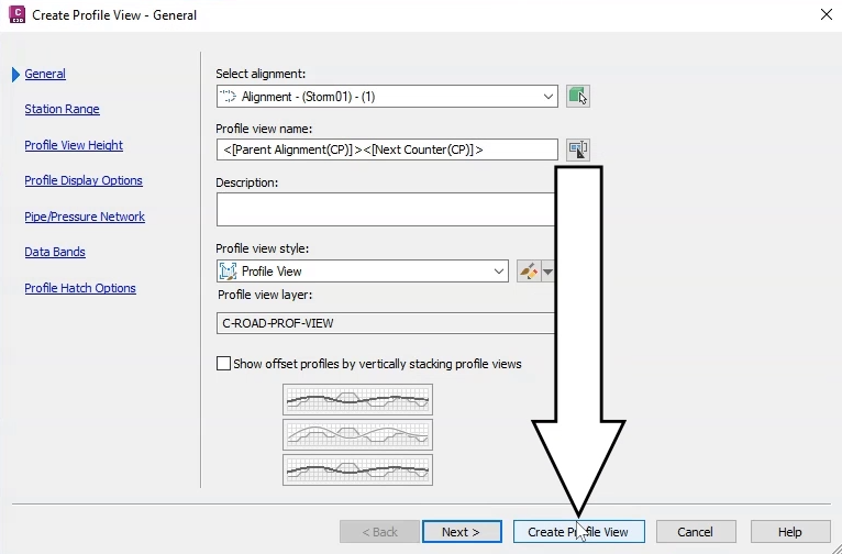
In the Create Profile View wizard, accept the defaults for this exercise and click Create Profile View.
04:11
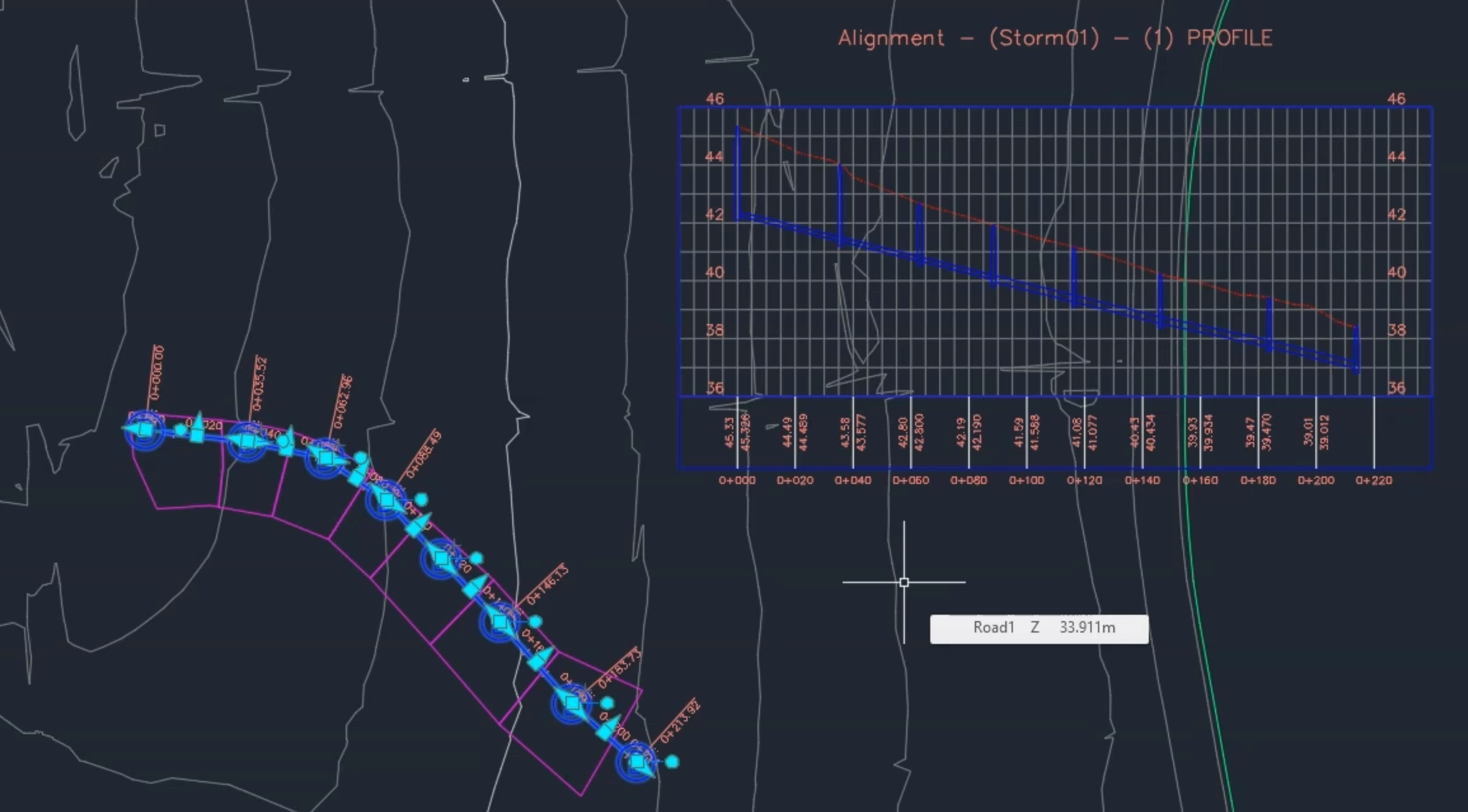
The profile view appears in the drawing attached to the cursor.
04:16
Click and drag to an open area in the drawing and then click again to place the view.
04:22
Here, you can see the updated pipe sizes and the reduced invert that was designed in InfoDrainage,
04:28
as well as the updated cover level.


 .
.