Step-by-step:
InfoWater Pro can test for chemical propagation in a water quality modeling simulation. The movement of water quality constituents is tracked throughout the network during an extended period simulation. Substances such as chlorine, total dissolved solids, nitrates, sodium, fluoride, and more can all be studied. In this exercise, you will perform a chlorine analysis.
- Open the appropriate .aprx file in ArcGIS Pro.
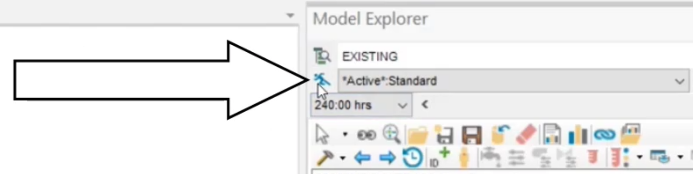
- From the ribbon, InfoWater Pro tab, Project panel, click Initialize.
- Set up the simulation options. In the Model Explorer, Operation tab, expand Simulation Options.
- Double-click WQ_AGE, Water Age Analysis.
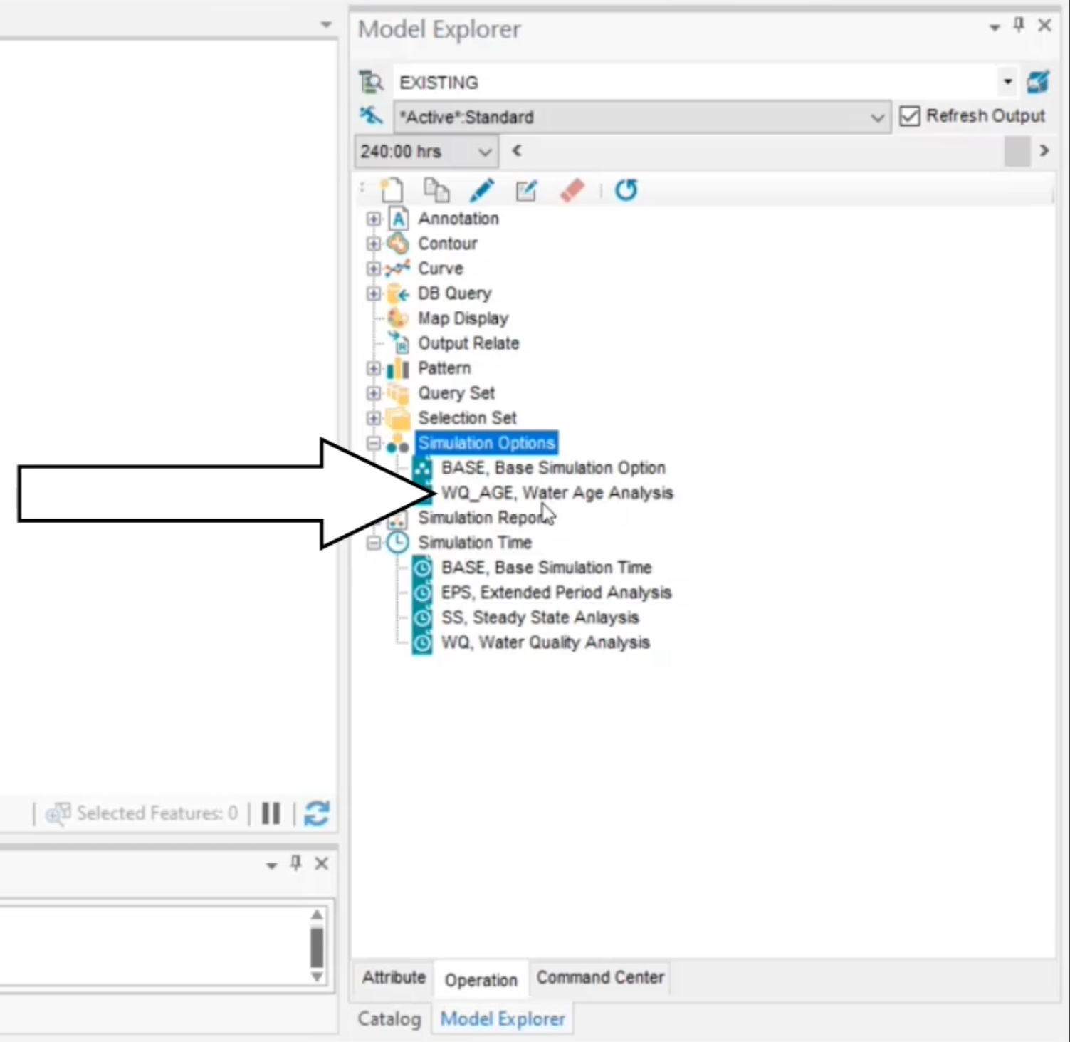
- In the Simulation Options dialog box, click Clone.

- In the New Simulation Options dialog box, New ID field, enter, “WQ_CL, Chlorine Analysis”.
- Click OK.
- From the Quality tab, set the WQ Tolerance to 0.001.
- Set the Mass Unit to mg/L.
- Set the Global Bulk coefficient to -1.
- Set the Global Wall coefficient to -0.5.
Recall that bulk and wall coefficients represent growth or decay rate for the constituent due to reactions between the chemical and the bulk flow of water or tank walls, respectively. Since both of these values are negative, these are decay rates.
- Click OK.

- Set the chlorine concentration for the reservoir in the network. In the map, select reservoir WTP100.
- In the Model Explorer, Attribute tab, expand Tools.
- Select Initial Water Quality.

- In the Reservoir Initial Quality dialog box, enter 1.2.
- Click Create.
This represents a constant chlorine concentration of 1.2 mg/L leaving the treatment plant.
- Run the simulation. In the Model Explorer, click Run.
- In the Run Manager, Standard tab, expand Simulation Options.
- Select WQ_CL, Chlorine Analysis.
- Expand Time Setting.
- Select WQ, Water Quality Analysis.
- Click Run.
- Click OK once the simulation is successfully completed.

- View the results of the chlorine analysis simulation.
- Select a junction in the map.
- In the Model Explorer, Attribute tab, click Graph.

- In the Report Manager dialog box, set the graph parameter to Chlorine.
- Click New.

- In the Output Report/Graph dialog box, click Tabular Report.
- Select Junction Range.
- Under Data Scope, select Complete Report/Graph.
- Click Open.

- In the Report Manager, set the parameter to Chlorine.
- In the table, select the Max. Value column header so the entire column is highlighted.
- Right-click the Max. Value column header.
- Select Data Histogram Plot.
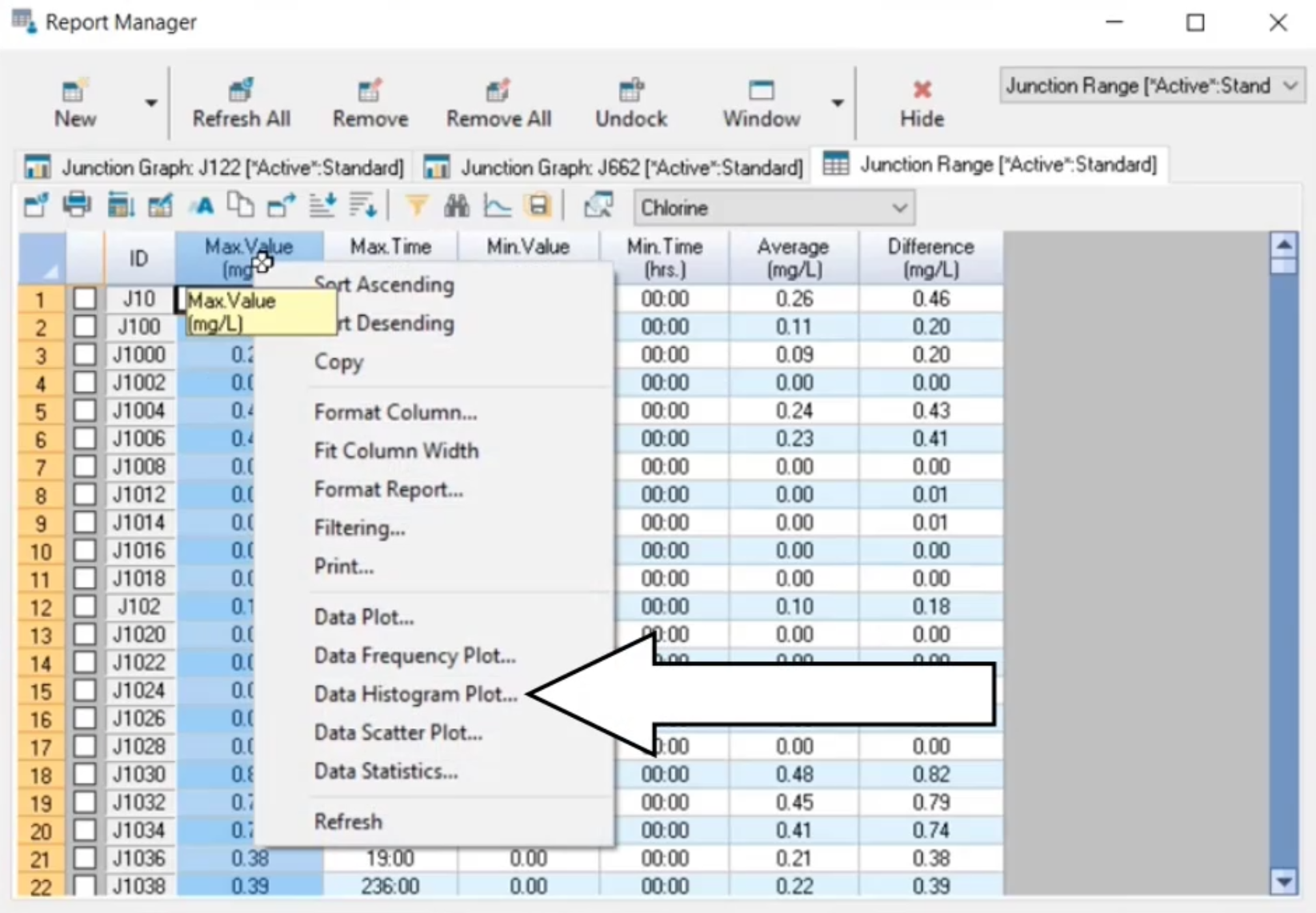
- In the Data Histogram of Max. Value dialog box, select By Interval.
- Set the value to 0.5.
- Click Classify.

This histogram now details the chlorine residual distribution in the system using 0.5 mg/L classes.
- Click Hide to close the Report Manager.


