00:03
Pressure zone information is useful for viewing output data by zone.
00:07
You can assign zone attributes to all features in the model from a GIS dataset
00:13
to begin double click the desired project dot APR X file to open Argi
00:20
Once the project starts,
00:21
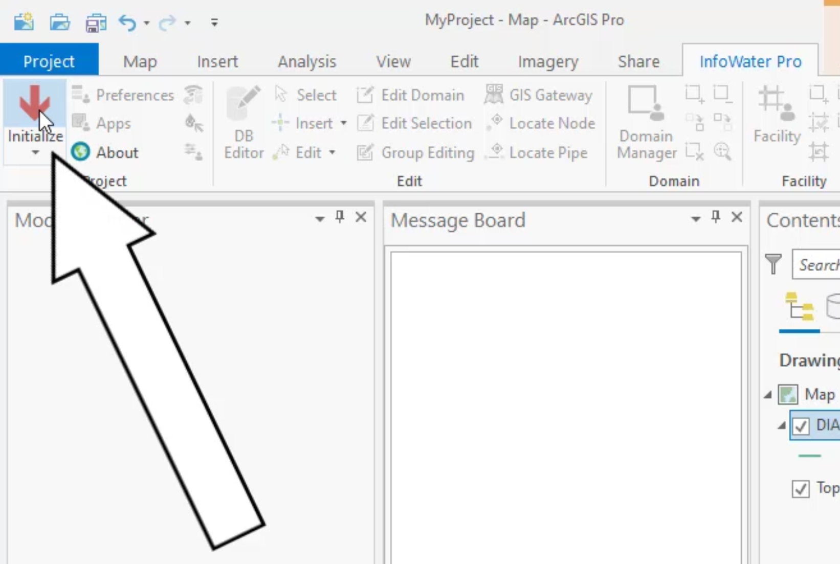
click the info water pro tab to open the info water pro ribbon.
00:27
In the project panel, click initialize
00:39
navigate to and open the dot GDB file you need
00:43
for this exercise, select pressure zones and then click OK.
00:49
In the selection panel, click select by attributes
00:53
in the select by attributes, dialogue,
00:55
ensure that input rows is set to pressure zones and
00:59
that the selection type is set to new selection.
01:05
Next, you need to add an expression,
01:07
click plus new expression. This is called plus add clause. In some versions of
01:13
and the tools for building an expression appear,
01:17
expand the ware dropdown and select zone.
01:22
Then in the next dropdown select is equal
01:26
in the final field, enter one
01:29
click apply and then OK to execute the expression
01:36
zoom out to see that pressure zone, one is now selected in the map and highlighted
01:43
back in the selection panel. Click select by location,
01:48
click and drag the title bar of the select by location dialogue so
01:51
that you can see the highlighted pressure zone as you configure these options,
01:57
then expand the input features, drop down and select valve,
02:03
then expand relationship and select completely within
02:10
set the selecting features to be pressure zones and the
02:13
selection type to be add to the current selection.
02:23
an error message appears
02:25
this case, it is because there are no valves in pressure zone. One
02:30
close the error message
02:32
select other features in pressure zone. One
02:36
change the input feature layer to junction
02:38
and then click apply
02:41
in the model. The junctions are highlighted.
02:43
Repeat this for tank
02:50
Be sure to click apply after each change,
02:55
each attribute that you add becomes highlighted in pressure zone.
02:58
One until all features that are completely within the zone are highlighted.
03:04
Close the dialog box.
03:06
Keep in mind that these are argi
03:11
on the info water pro ribbon in the domain panel, click the selection to domain icon.
03:18
This command is useful when using Argi
03:20
Pro selection tools within the info water pro environment.
03:26
S pro selections of info water pro elements can be turned into a domain.
03:32
Notice also that the highlight color changed when it became a domain
03:38
Click edit domain to open the edit attribute,
03:41
interactive table report for objects in the domain
03:46
on the junction tab,
03:47
click the zone column heading to select and highlight all the column cells.
03:52
Then in the toolbar click the block editing icon to open the group,
03:57
editing number dialogue
04:00
in the operation group enable set equal and then enter a value of one
04:08
All junctions now have an assigned zone of one
04:13
repeat this process for the tank reservoir pump and pipe tabs
04:18
Be aware that the valve tab is not accessible since there are no valves in the domain.
04:25
Click save all tabs to save your changes and then exit the domain editor
04:34
selection panel. Click clear to deselect the arc
04:38
GS pro selections that you made
04:41
on the info water pro ribbon
04:43
domain panel. Click clear domain