Collaborate using factory design utilities
Note: This exercise uses the Production C.iam layout developed in the Create a Factory Utility Design Layout exercise from the previous unit. If you have not already done so, you will need to complete that exercise first.
Task 1: Simplify the layout to share in Revit
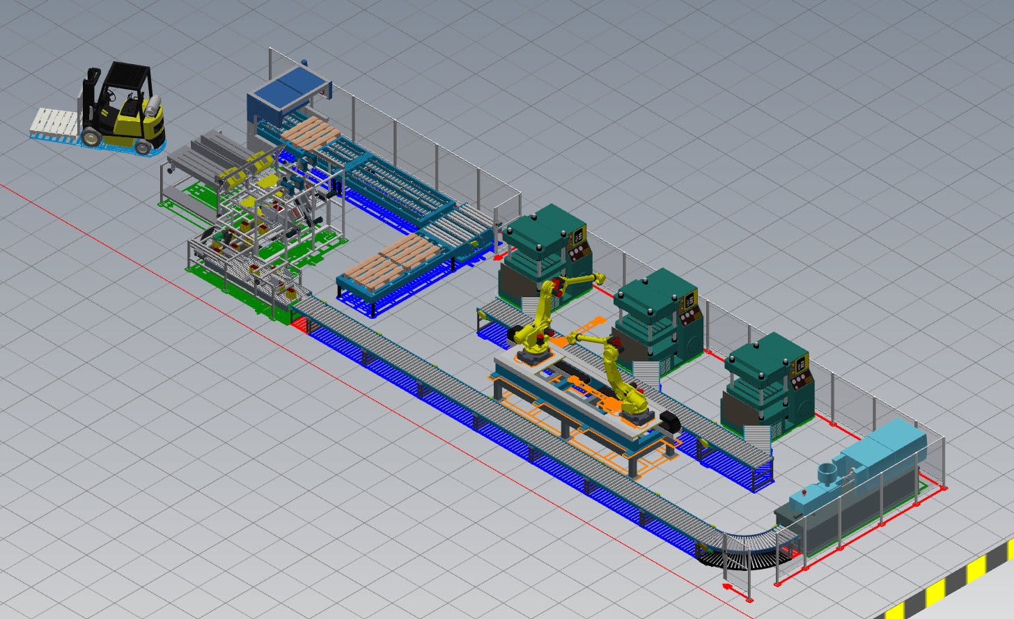
The first goal is to share your layout with the architectural team working in Revit. They need a simple space reservation for all the assets in this layout.
- Continue with or open Production C.iam (developed in the previous unit's exercise) in Inventor.
- In the Assemble tab>Simplification panel, click Simplify.
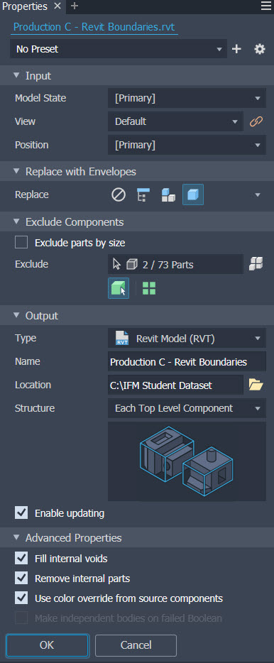
- In Properties, do the following:
- Under Replace with Envelopes, select Each Part.
- Under Excluded Components, clear the checkmark for Exclude parts by size.
- Under Output, set the Type to Revit Model (RVT). Enter Product C – Revit Boundaries for the Name and set Structure to Each Top Level Component. Confirm Enable updating is checked.
- Under Advanced Properties, check Fill internal voids, Remove internal parts, and Use color override from source components.
- Click OK to execute the command.
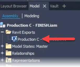
- In the Model Browser, review the Revit Exports entry. Note: This entry can be updated if changes are made to the layout.
Task 2: Import the Revit model into Inventor
The second goal is to import the architectural Revit model into our Inventor layout to see how your proposed layout will fit inside the building.
- In the Factory tab>Layout panel, click Add DWG Underlay and select Factory Footprint.dwg from the dataset.
- In the Assemble tab>Component panel, click Place Imported CAD Files and select the Mannheim_Revit.rvt file located in the dataset. If prompted for the version of Revit, select Open Anyway.
- Note: It is recommended to access critical data from a shared BIM360 project site via the Autodesk Desktop Connector. This will assure the correct design file is utilized and will also provide an update workflow if the building model is ever altered.
- In the Import dialog, confirm that Reference Model is selected as the Import Type and allow the view list to load. This will take a few moments.
- In the 3D View drop-down list, select section view. Under Categories, uncheck Entourage, Generic Models, Parking, Planting, and Site, then click OK.
- Click OK when notified about the large number of elements.
- When the building appears on your cursor, right-click and select Place Grounded at Origin, then press <Esc>.
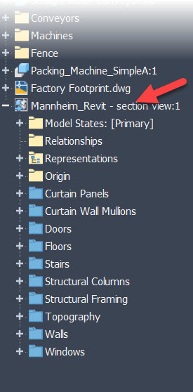
- In the Model Browser, expand the Mannheim_Revit building and review the available content.
- Save and close all files.


