Better machine design with Inventor Design Accelerators
Description
Simulation technologies are very powerful, but for purchased fasteners or machine components that use standard gear tooth profiles, bearings, chains, or springs simulation aren’t the most efficient solutions. The answers to selecting those types of components have been cataloged for decades in handbooks and reference materials. We’ll try out several of the Design Accelerators in Inventor that use time-tested performance standards to size and select components. These tools can also shorten the design process by creating multiple features at once even through multiple components in an assembly. If you design machinery, you need to be aware of these tools.
Design Accelerators
Design Accelerators are a standards-based tool for creating or calculating machine components based on the engineering requirements of the design. Each of the tools is either a Calculator which can give you the information on what is required of a machine component or a Generator which can based on basic input or calculators create the digital model of the standard component.
Created in the context of an assembly, the Design Accelerator use your inputs to determine what standard components to select for fasteners bearings belts and chef components. They can also use your engineering requirements to develop custom components based on standard materials, gear profiles and using metal profiles to build frames.
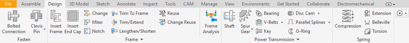
The Design Accelerator tools can be found on the Design tab of the ribbon when working in an assembly file. The tools are segmented into Fasten, Frame, Power Transmission, and Spring panels. The panels do a great job of segmenting the based on their primary use in the type of component they generate or calculate.
Power transmission
This panel focuses on the chefs the components that support them are connected to them or drive the rotation. Expanding the panel will reveal a number of calculators and machinery handbook.
Getting hands on
Expand the data sets if they are not already installed on the lab system. The path you choose will not matter as long as you can locate the files and most importantly the project file.
Activate the Better Machine Design.ipn file to be able to access the files required for this lab.
Shaft generator - Exercise
Creating and editing a shaft
When using Inventor, most users begin to develop a shaft by drawing a half section of the component and revolving it. The shaft generator focuses on building the shaft in sections and includes the ability to add specialized features such as wrench flats or axial holes. With the ability to develop internal geometry the shaft generator is also very useful for creating hubs and other rotating components that have a consistent profile. Along with the geometry there are calculator tools that allow you to validate the size of the shaft elements based on the loads that will be applied to it.
- Open the Belt Driven Reducer – Shaft.iam file from the Workspace folder.
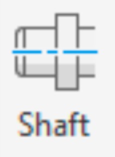
- Switch to the Design tab, hold the Ctrl key, and start the Shaft generator tool from the Power Transmission panel. Note: Holding the Ctrl key will start the tool with the default shaft configuration.
- Click anywhere in the design window to place the shaft preview. Review the shaft segments in the dialog and try to relate them to the shaft preview.
- Explore the pull-down menu at the beginning and the end of the segments. These pull-downs along with the segment shape define the segments and how they transition to others.
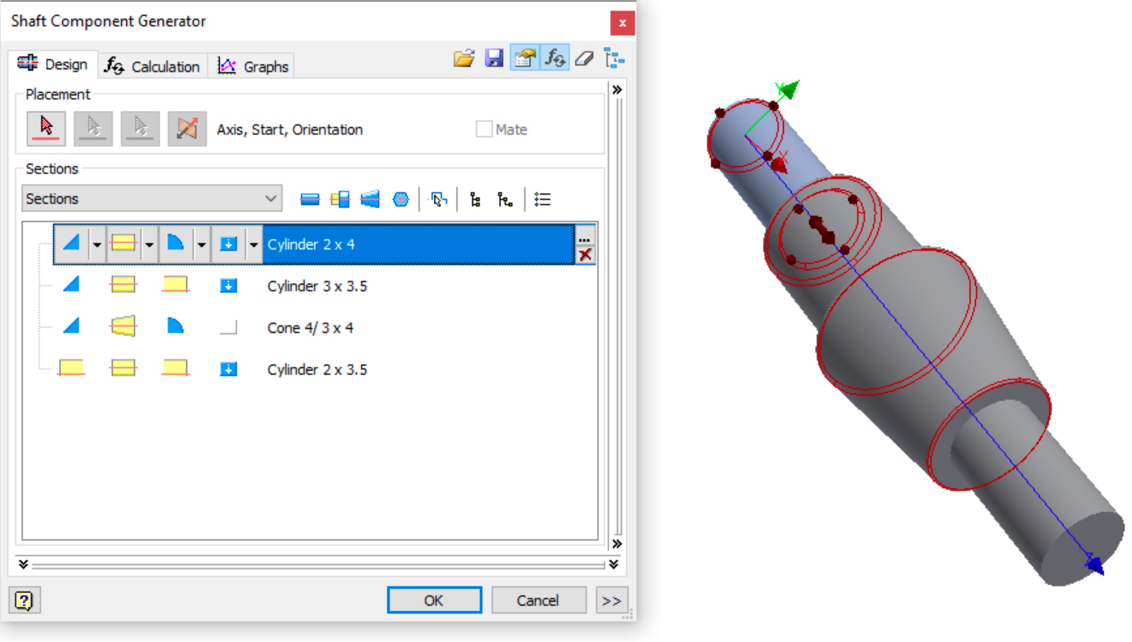
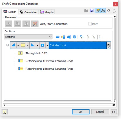
- Modify the first segment (top) by clicking the description. Set the Diameter to .75 and the length to 1.3.
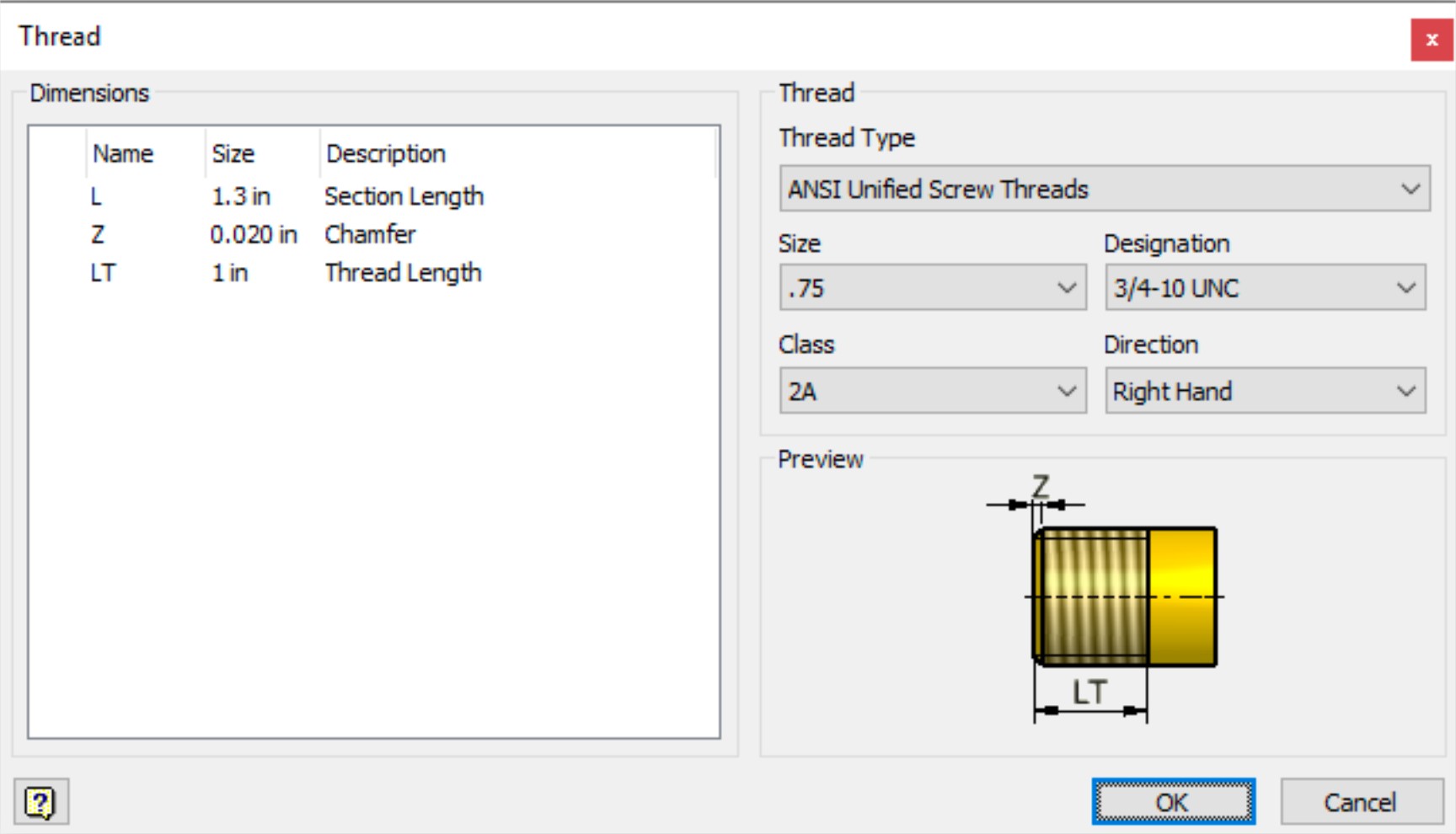
- Change the Chamfer left end treatment to a threaded segment with a Thread Length (LT) of 1.0.
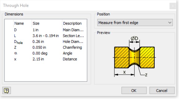
- Edit or create the second, rectangular segment with a diameter of 1.0 and a length of 3.41. There are no end treatments. Select the Section Feature drop-down (blue icon) and choose Add Through Hole, setting the Hole Diameter to .26 and the Distance to 2.15 from the first edge.
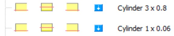
- Edit or add two cylindrical sections with no end treatments with a diameter of 3.0 and a length of .80 and another segment of 1.0 and .06.
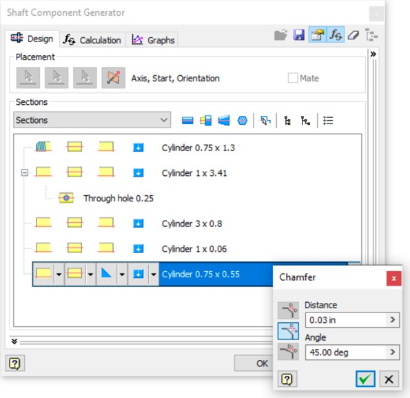
- Add a final cylindrical segment with a diameter of .75 and a length of .55.
- Add a Chamfer right end treatment with a distance of .03 and an angle of 45.
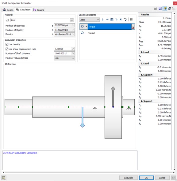
- Click on the Calculation tab and change the Radial force to a 6 lbs. ft moment.
- Add an opposite (-6 lbforce) moment approximately where the hole in the shaft is.
- Move the supports to either side of the large segment.
- Click Calculate and review the results on the Results tab.
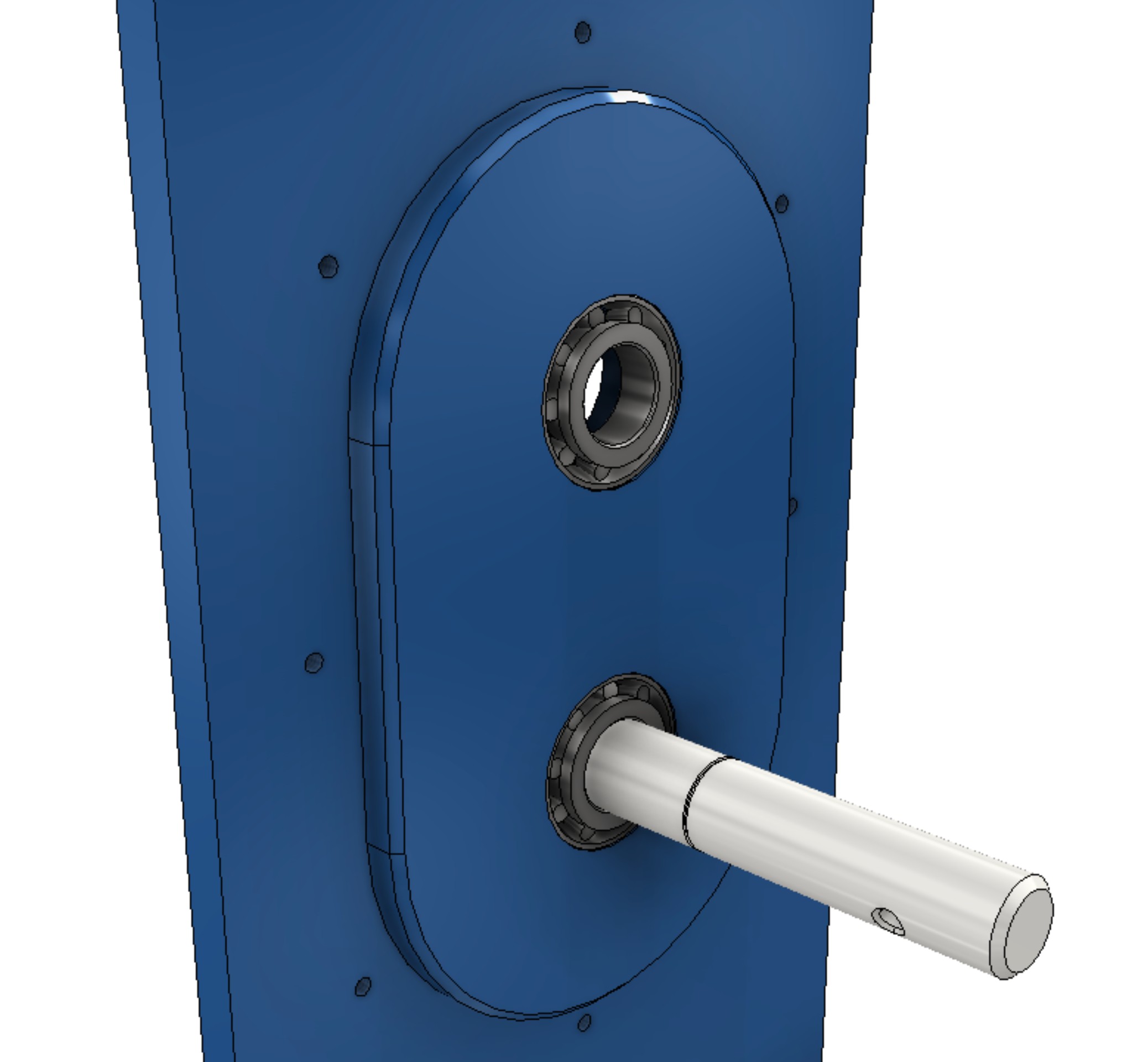
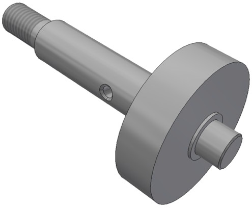
- Click OK to generate the shaft. Then click a location in the design window to place the completed shaft.
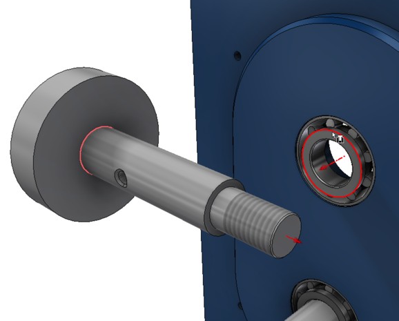
- Create an Insert constraint between thread side edge of the large segment and the inner race of the top bearing.
- Right-click on the lower shaft and select Edit Using Design Accelerator.
- Review the elements of the shaft including the presence of three different section features related to the shaft.
- Click Cancel to avoid making a change to the shaft definition.
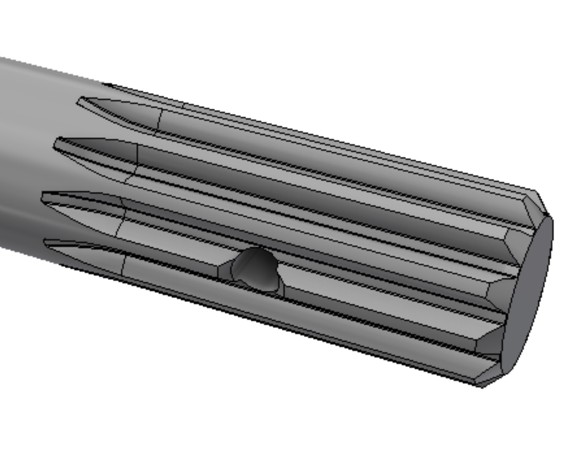
Splines can be added to a shaft feature and/or to a hole passing through a component that mates to the shaft. These splines are based on standards and can be sized based on calculating the engineering requirements placed on the spline to keep the shaft coupled.
- In the Power Transmission panel, find the Involute Splines tool (Parallel Splines pull-down) and start it.

- Select the cylindrical face with the through hold as Reference 1.
- Select the end face of the shaft for Reference 2.
- Set the Splines Type to: ANSI B92.1 – 37.5 deg with 12 splines.
- Deselect the second Objects to Generate which would create an internal profile on a second component.
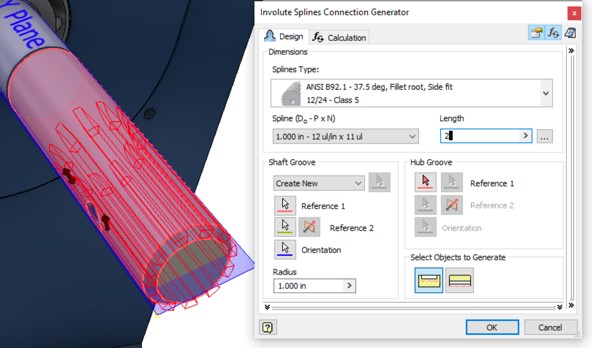
- Click OK to confirm the new features and OK again to generate the feature.