Overview of loads and constraints in Nastran
The accuracy of an FEA solution is highly dependent on the correct application of loads and constraints. Over, or under, constrained models typically generate worthless results. It's important to understand the mechanics of the model before adding the boundary conditions. The goal of these boundary conditions is to mimic the external forces acting on a structure and how it’s being supported in space.
Types of loads generally available
Loads exist in the finite element analysis program so that you can simulate the forces, motion, temperature, or thermal loads that the geometry is anticipated to withstand. Depending on the analysis type you select, certain loads may not be applicable. For instance, applying a structural force load in a thermal analysis is inconsequential.
- Note: Depending on the program, it may either limit the display of the types of loads available to only show those supported by the chosen analysis type or provide messaging if the load applied is not applicable to the currently selected analysis type.
Certain analysis types might accommodate different types of loads. For instance, a thermal stress analysis can allow for both structural loads (like forces and pressures) while at the same time allowing for thermal loads (such as temperatures and convection).
Structural loads
There will be some variability, depending on the specific finite element analysis package you are utilizing, but you can generally expect to find loads to fit your structural analysis. Inventor Nastran includes:
- Force
- Pressure
- Distributed load
- Hydrostatic load
- Moment
- Gravity
- Remote load
- Bearing load
- Centrifugal/rotational load
- Displacement/enforced motion
- Initial condition
- From output (loads from file)
There are a number of structural loads available to represent what the geometry is expected to withstand, and the loads can be applied in conjunction with one another – e.g., a model may have internal pressure, while at the same time another area of the model is subject to bearing loads.
Thermal loads
There will be some variability, depending on the specific finite element analysis package you are utilizing, but you can generally expect to find loads to fit your thermal analysis. Inventor Nastran includes:
- Body temperature
- Temperature
- Convection
- Radiation
- Heat generation
- Heat flux
- From output
There are a number of thermal loads available to represent what the geometry is expected to withstand, and the loads can be applied in conjunction with one another. With thermal analysis, there will generally be at least two loads – if you put heat into the model (e.g., with a temperature), there should also be a way for heat to leave the model (e.g., with convection), and vice versa. If the goal is to cool the model, somewhere else in the model there must be a source of heat. Otherwise, the temperature in the model will just spiral off to an unrealistically high temperature (if only a heat source is applied) or low temperature (if only a way to remove heat is applied).
Types of constraints
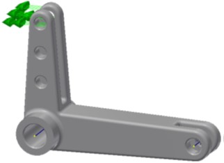
Constraints are used in the Autodesk Inventor Nastran environment to simulate the boundary conditions of the model in its working environment. Assigning the correct constraint to accurately describe its physical boundary conditions is critical. Incorrectly representing a boundary condition can affect the accuracy of the results. In general, constraints are used to simulate the true supports (rigid foundation), contacting geometry (adjoining structure), or other boundary conditions in a model. Constraints can be applied to the part’s face, edges, or vertices. Multiple constraints can be added to a model, as required.
- Note: The constraints that are used to define the model’s boundary conditions must not impose displacements, stresses, rigidity, or other behavior that would not be experienced in the model's working environment.
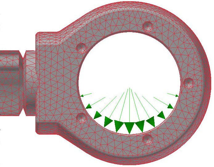
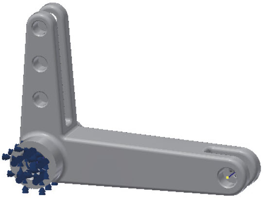
In the following model, a constraint was added to represent a pin that would be located through the lever component. This constraint fixes the model so that translational and rotational movement is prevented in all directions.
Autodesk Inventor Nastran supports the following types of constraints:
- Structural
- Pin
- Frictionless
- Response Spectrum
- Thermal
- Rigid (explicit)
Similar to materials and idealizations, you can drag and drop constraints to include them in an analysis subcase. Multiple constraints can exist in a subcase.
- Note: Pin and Frictionless constraints automatically create new coordinate systems. Pin will create a cylindrical coordinate system with the Z-axis running through the center of the cylindrical face selected. Frictionless creates a coordinate system with the Z-axis normal to the selected face and symmetry conditions applied.
Degrees of freedom
When assigning constraints, you also will select the degrees of freedom of the nodes associated with the selected entities being constrained. You can fully define how the constraint is constrained by enabling or disabling the degrees of freedom options. By default, the constraint is assigned using the Part 1 coordinate system. This is the model coordinate system that was set when the model was opened in the Autodesk Inventor Nastran environment. If a custom coordinate system was created in the Model Tree, it can be assigned for use in a new constraint.
There are four options that can be used to preset the degrees of freedom settings. Alternatively, you can explicitly enable or clear the degrees of freedom options to define the constraint, if one of these four options do not provide the correct degrees of freedom.
- Fixed: Constrains translation and rotation in all directions.
- No Translation: Prevents translation in any direction but enables rotation at each node on the selected entities.
- Free: Enables translational movement in any direction and rotation about any axis.
- No Rotation: Constrains nodal rotations for all axis directions but enables translational motion in any direction.
Solid elements do not have rotational degrees of freedom. Therefore, rotational constraints have no effect on solid elements. A single node of a solid element acts like a frictionless ball joint when fully constrained (fixed).
Symmetry options are available that enable you to define symmetry or anti-symmetry in the X, Y, or Z directions. It is recommended you verify the coordinate system to ensure that you are selecting the correct option.
Application of loads and constraints
Direction control
Load input is generally either normal to an element's face (e.g., with pressure) or can be oriented with respect to the model’s global coordinate system – a force, for example, could be specified in components of the x, y, or z direction.
At times, there might be situations where it is beneficial to define a new local coordinate system. In this way, loads (or constraints) can be applied in directions that are aligned to geometry features that do not necessarily align to one of the model’s original global axis directions. An example is shown in the image below.

Using a user-defined local coordinate system (LCS), it was possible to define the 45° face as the XZ plane. The force can then be applied normal to the face using the local -Y direction of this new LCS.
Multiple local coordinate systems can be defined, if necessary, to accommodate different regions of the model. Local coordinate systems are beneficial in that they can assist in allowing you to readily apply loads that may not align with the model’s global coordinate system.
When defining a load direction, the Geometric entities option lets you choose a reference sketch or edge to apply the force vector. This is very helpful when the orientation doesn’t match an existing coordinate system.
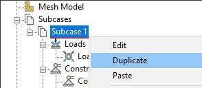
Analysis subcases
It is not uncommon that an object is subject to multiple loads that could impact the geometry at the same time: gravity, pressure, forces, and perhaps temperature, as an example. It could also be the same load (e.g., a force) that needs to be examined in different magnitudes and/or directions.
While it is good to know how the structure will react to all these loads together, it is sometimes necessary to know how the model reacts to each of these independently – such that you can determine which causes the most (and the least) impact to your design.
Subcases allow you to analyze different load cases within the same Analysis and compare the results. The constraints can also be varied from subcase to subcase. The Idealizations, Mesh, and Materials must remain the same for all subcases in the Analysis. This process is much more efficient than starting over each time with a new analysis.