00:01
PAWEL PULAK: Adjusting preferences and tolerances
00:04
In this video, we will step through the process
00:07
of setting recommended model generation
00:09
and meshing parameters in robot, changing local mesh settings,
00:14
and modifying the tolerance of model generation.
00:17
I'm working in robot structural analysis
00:19
using the small Medical Center model exported from Revit.
00:23
By default, the analysis in robot
00:25
is preceded by automatic model generation,
00:28
including machine panels intersecting elements where
00:31
necessary and applying loads.
00:34
It results in a finite analysis method
00:36
model ready for the solver.
00:39
Some default settings of model generation and finite element
00:42
mesh generators can be set in job preferences.
00:46
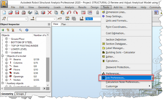
In Tools, select Job preferences.
00:50
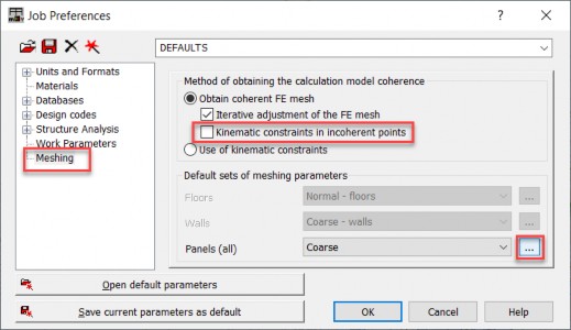
In the Job preferences dialog box,
00:52
select meshing on the left.
00:54
And then switch off Kinematic constraints
00:57
and incoherent points, so that robot
00:60
will be forced to iteratively adjust
01:02
the coherence of the finite element mesh.
01:06
Then next to Panels, click the Browse button
01:09
which opens the Meshing options dialog box.
01:12
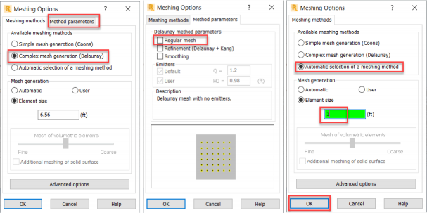
Activate Complex mesh generation.
01:15
And then in the Method parameters tab,
01:18
switch off Regular mesh.
01:20
This makes meshing less sensitive
01:22
to possible model inaccuracies.
01:26
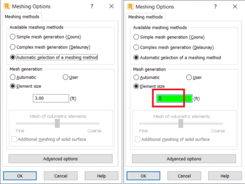
Return to the Meshing methods tab and activate
01:29
Automatic selection of a meshing method.
01:33
Finally, specify the element size equal to 3 feet,
01:37
and click OK to accept these changes.
01:45
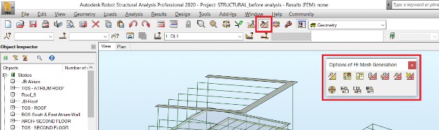
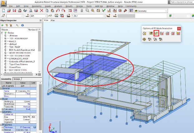
Some more detailed changes related to a finite element
01:48
mesh can be made in the Options of FE Mesh generation toolbar.
01:53
It's possible to change the mesh parameters for selected panels.
01:57
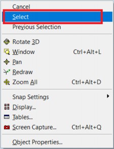
For instance, I might want to change the finite element
02:02
I'm going to right click and select Select, and then
02:08
In the Options dialog box, I select Meshing options
02:12
and change the element size to 2.
02:16
This change is applicable only to the selected panel.
02:20
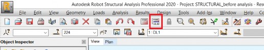
This toolbar enables also to be able to generate or delete
02:24
existing mesh or to freeze and unfreeze
02:27
existing mesh for selected panels.
02:30
It's also possible to run the full model
02:32
generation without running finite element analysis.
02:39
Settings related to model generation
02:41
can also be modified.
02:43
I'm choosing the Analysis parameters icon
02:46
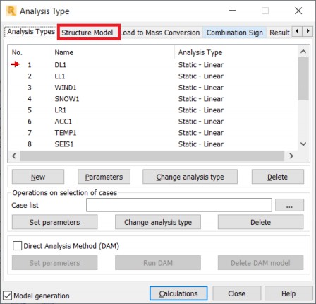
to open the Analysis type dialog box.
02:49
The Analysis type dialog box is opened with the Analysis type
02:53
tab active, where load cases and combinations defined
02:57
in the model are displayed.
02:59
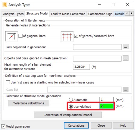
Select the Structural model tab to access parameters
03:02
related to model generation.
03:06
For example, I want to change from automatic to user defined
03:10
tolerances of structure model generation
03:13
and set the tolerance value equal to 2.
03:17
A higher tolerance may be necessary in case
03:20
of moral inaccuracies.
03:23
You can now start to work on additional analysis.