• AutoCAD

Getting started with AutoCAD

Becoming familiar with the AutoCAD user interface is your first step in getting to know the software. Tour the ribbon and try out the Command line. Learn how to open a drawing or create a new one, and then you can access them remotely. Create simple geometry using construction lines, grids, and the UCS as guides.


After you launch AutoCAD, click New on the Start tab to begin a new drawing, or Open to work on an existing drawing.

Drawing Tabs

The new drawing, Drawing1, starts on a new tab that's just above the drawing area. You can click the tabs to switch between several open drawing files and the Start tab.

An asterisk (*) next to the drawing name indicates that the drawing needs to be saved. A quick way to close any drawing is to click the X control on its tab.

Go ahead and experiment with starting and opening drawings, and switching between the tabs. You can also drag the drawing tabs to reorder them.

The Ribbon

AutoCAD includes a standard tabbed ribbon across the top of the application. You can access nearly all the commands presented in this guide from the Home tab. In addition, the Quick Access toolbar shown below includes familiar commands such as New, Open, Save, Print, and Undo.

Note: If the Home tab is not the current tab, go ahead and click it.

The Command Window

At the heart of the program is the Command window, which is normally docked at the bottom of the application window. The Command window displays prompts, options, and messages.

You can enter commands directly in the Command window instead of using the ribbon, toolbars, and menus. Many long-time users prefer this method.

Notice that as you start to type a command, it completes automatically. When several possibilities are available such as in the example below, you can make your choice by clicking it or using the arrow keys and then pressing Enter or the Spacebar.

The Mouse

Most people use a mouse as their pointing device, but other devices have equivalent controls.

Tip: When you look for an option, try right-clicking. Depending on where you locate your cursor and whether you're in a command, the shortcut menu that displays provides relevant commands and options.

New Drawings

You can easily conform to industry or company standards by specifying settings for text, dimensions, linetypes, and several other features. For example, this backyard deck design displays two different dimension styles.

All these settings can be saved in a drawing template file. Click New to choose from several drawing template files:

  • For imperial drawings that assume your units are inches, use acad.dwt or acadlt.dwt.
  • For metric units that assume your units are millimeters, use acadiso.dwt or acadltiso.dwt.

The "Tutorial" template files in the list are simple examples for the architectural or mechanical design disciplines with both imperial (i) and metric (m) versions. You might want to experiment with them when you start creating dimensions.

Most companies use drawing template files that conform to company standards. They will often use different drawing template files depending on the project or the client.

Create Your Own Drawing Template File

You can save any drawing (.dwg) file as a drawing template (.dwt) file. To create a new drawing template file based on an existing one, open the existing drawing template file, modify it, and then save it again with a different filename.

If you work independently, you can develop your drawing template files to suit your working preferences, adding settings for additional features as you become familiar with them. To modify an existing drawing template file, click Open, specify Drawing Template (*.dwt) in the Select File dialog box, and choose the drawing template file.

Important: If your company has already established a set of drawing template files, check with your CAD manager before modifying any of them.

Units

After you start a new drawing, you'll first decide what the length of one unit represents—an inch, a foot, a centimeter, a kilometer, or some other unit of length. For example, the objects below could represent two buildings that are each 125 feet long, or they could represent a section from a mechanical part that is measured in millimeters.

Unit Display Settings

After you decide what unit of length that you want to use, the UNITS command lets you control several unit display settings including the following:

  • Format (or Type). For example, a decimal length of 6.5 can be set to display as a fractional length of 6-1/2 instead.
  • Precision. For example, a decimal length of 6.5 can be set to display as 6.50, 6.500, or 6.5000.

If you plan to work in feet and inches, use the UNITS command to set the unit type to Architectural, and then when you create objects, specify their lengths in inches. If you plan to use metric units, leave the unit type set to Decimal. Changing the unit format and precision does not affect the internal precision of your drawing. It affects only how lengths, angles, and coordinates are displayed in the user interface.

Tip: If you change a setting for the unit display or any other setting, you can save the settings in a drawing template file. Otherwise, you'll need to change the settings for each new drawing.

Model Scale

Always create your models at full size (1:1 scale). The term model refers to the geometry of your design. A drawing includes the model geometry along with the views, notes, dimensions, callouts, tables, and the title block displayed in the layout.

You'll specify the scale for printing a drawing on a standard-sized sheet later, when you create the layout.

Recommendations

  • To open Help with information about the command in progress, simply press F1.
  • To repeat the previous command, press Enter or the Spacebar.
  • To see various options, select an object and right-click, or right-click a user interface element.
  • To cancel a command in progress or if you ever feel stuck, press Esc. For example, if you click in the drawing area before entering a command, you'll see something like the following:

The easiest way to change your view is by using the wheel on your mouse.

  • Pan a view in any direction by holding the wheel down and then moving your mouse.
  • Zoom in or out by rolling the wheel.

Tip: When you zoom in or out, the location of the cursor is important. Think of your cursor as a magnifying glass. For example, if you position the cursor in the upper-right area of the floor plan as shown below, rolling the mouse wheel magnifies that area without shifting it.

You can step back through a number of previous views by entering ZOOM in the Command window and then specify the Previous option.

A fast way to do this is by entering a command alias for the command. For example, the command alias for ZOOM is Z.

  1. Type Z in the Command window and press the Spacebar or Enter.
  2. Then type P and press the Spacebar or Enter.

The previous view displays. Also note that typing a command or a command alias followed by pressing the Spacebar or Enter key is often abbreviated with a description like this: "Enter the ZOOM command."

The other commonly used options in the ZOOM command are Window and Extents. The Window option enables you to specify a rectangular window of the area that you want to display. The Extents option displays all of the objects in the drawing area.

View or Modify Drawings from Remote Locations

It can be helpful to be able to access your drawing files while on a job site, the shop floor, at a meeting, or when travelling. With your AutoCAD or AutoCAD LT subscription, you can view, create, and modify drawings on any of these devices:

  • Your primary desktop or laptop in your office location with AutoCAD or AutoCAD LT installed
  • Another computer at a different site or at home using the AutoCAD web app on your web browser
  • Your smartphone or tablet in a remote location using the AutoCAD mobile app

If you think you'll need to access your drawings from a remote location, try using the Save to Web & Mobile and Open from Web & Mobile commands.

To be able to access your drawings from a remote location, do one of the following:

  • Download the free mobile app to your mobile device and sign in with the same Autodesk ID that you use for your AutoCAD or AutoCAD LT subscription.
  • From a tablet or a different computer, use your web browser (64-bit Chrome or Firefox) to log in to https://web.autocad.com.

Access Drawings from a Cloud Storage Account

If you have an account with a cloud storage provider, you can add it to your Places bar in AutoCAD file selection dialog boxes for direct navigation to the drawings in your cloud storage account. Simply right-click within the Places bar and enter a name and path for the navigation shortcut.

Navigation shortcuts for Microsoft OneDrive, Box, Dropbox, and Google Drive automatically display in your Places bar if you have an account.

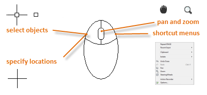
You can create a lot of different types of geometric objects in AutoCAD, but you only need to know a few of them for most 2D drawings.

Tip: If you want to simplify the display while you create geometric objects, press F12 to turn off dynamic input.

Lines

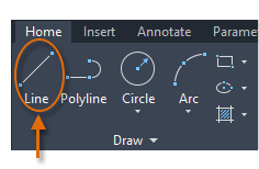
The line is the most basic and common object in AutoCAD drawings. To draw a line, click the Line tool.

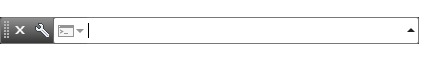
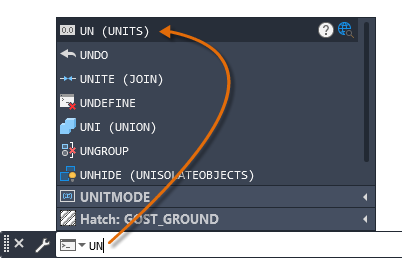
Alternatively, you can type LINE or just L in the Command window, and then press Enter or the Spacebar.

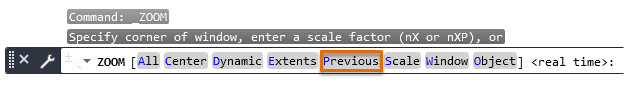
Notice the prompt in the Command window for a point location.

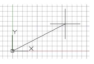
To specify the starting point for this line, you would type in the Cartesian coordinates 0,0. It's generally a good idea to locate one corner of your model at 0,0, which is called the origin point. To locate additional points, you could specify additional X,Y coordinate locations in the drawing area, however more efficient methods for specifying points are available, and will be presented in the Precision topic.

After you specify the next point, the LINE command automatically repeats itself, and it keeps prompting you for additional points. Press Enter or the Spacebar to end the sequence.

Grid Display

Some people like working with grid lines as a reference, while others prefer working in a blank area. To turn off the grid display, press F7. Even with the grid turned off, you can force your cursor to snap to grid increments by pressing F9.

Lines as Construction Aids

Lines can serve as reference and construction geometry such as

  • Property line setbacks
  • The mirror line of a symmetrical mechanical part
  • Clearance lines to avoid interferences
  • Traversal path lines

Circles

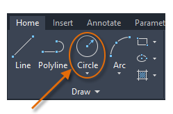
The default option of the CIRCLE command requires you to specify a center point and a radius.

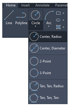
Additional circle options are available from the drop-down:

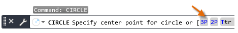
Alternatively, you can enter CIRCLE or just C in the Command window and click to choose an option. If you do, you can specify a center point, or you can click one of the highlighted command options as shown below.

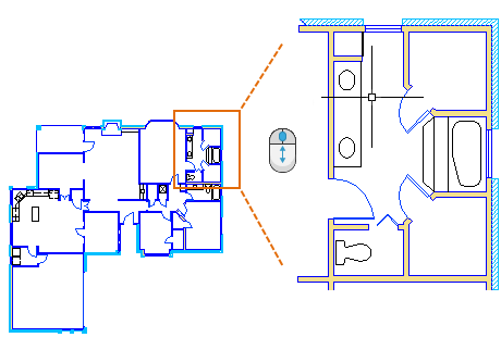
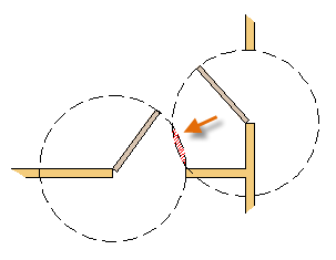
Circles can be useful as reference geometry. For example, you can see that the two doors in the illustration can interfere with each other.

Polylines and Rectangles

A polyline is a connected sequence of line or arc segments that is created as a single object.

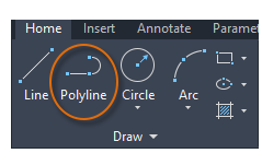
Use the PLINE command to create open or closed polylines for

  • Geometry that needs to have fixed-width segments
  • Continuous paths for which you need to know the total length
  • Contour lines for topographic maps and isobaric data
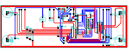
  • Wiring diagrams and traces on printed circuit boards
  • Process and piping diagrams

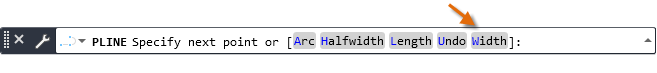
Polylines can have a constant width or they can have different starting and ending widths. After you specify the first point of the polyline, you can use the Width option to specify the width of all subsequently created segments. You can change the width value at any time, even as you create new segments.

Here is an example of a printed circuit board in which the traces were created with wide polylines. The landing pads were created with the DONUT command.

Polylines can have different starting and ending widths for each segment as shown here:

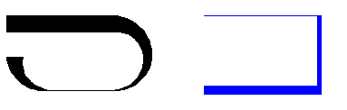
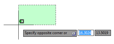
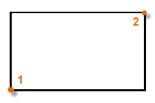
A fast way to create closed rectangular polylines is to use the RECTANG command (enter REC in the Command window).

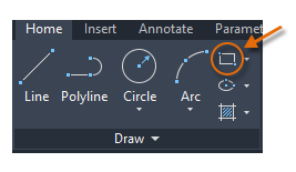
Simply click two diagonal points for the rectangle as illustrated. If you use this method, turn on grid snap (F9) for precision.

The User Coordinate System (Optional)

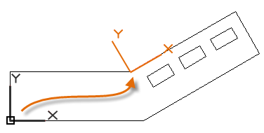
The user coordinate system (UCS) icon indicates the direction of the positive X and Y axis for any coordinates that you enter, and it also defines the horizontal and vertical directions in a drawing. In some 2D drawings, it can be convenient to click and place the UCS to change the origin point and the X or Y axis.

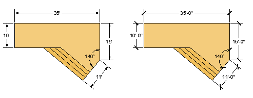
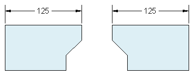
For example, by reorienting the UCS, you can create rectangles that are automatically aligned with the X axis as shown.

To restore the user coordinate system to its original location, enter UCS in the Command window and press Enter to specify the default <World> option.

Hatches and Fills

In AutoCAD, a hatch is a single, compound object that covers a specified area with a pattern of lines, dots, shapes, a solid fill color, or a gradient fill.

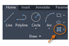
When you start the HATCH command, the ribbon temporarily displays the Hatch Creation tab. On this tab, you can choose from more than 70 industry-standard imperial and ISO hatch patterns, along with many specialized options.

The simplest procedure is to choose a hatch pattern and scale from the ribbon, and click within any area that is completely enclosed by objects. You need to specify the scale factor for the hatch to control its size and spacing.

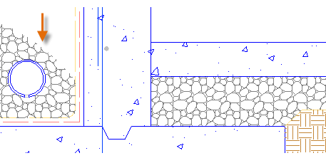
After you create a hatch, you can move the bounding objects to adjust the hatch area, or you can delete one or more of the bounding objects to create partially bounded hatches:

Tip: If you set a hatch pattern to be a solid or gradient fill, also consider setting a transparency level on the Hatch Creation tab for interesting overlap effects.

Here are some examples of how you can use solid-fill hatches:

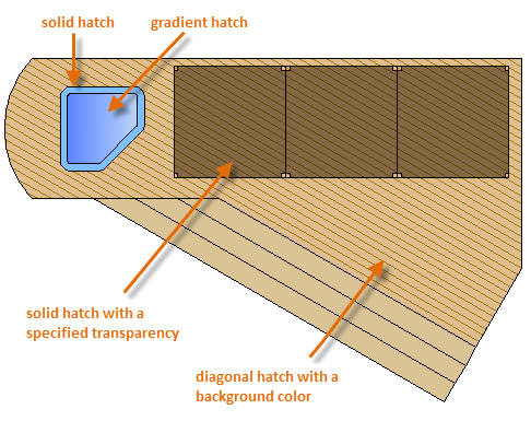
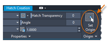
Tip: If you need to align the pattern in a hatch, which might be the case with the decking boards above, use the Set Origin option to specify an alignment point.

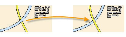
For overlapping hatches, fills, wide polylines, and text objects, use the DRAWORDER command to determine which objects are on top or below the others. For example, you probably want the yellow highway to cross the blue river rather than the other way around.

You can access several draw order options from the Modify panel on the ribbon. Click to expand the Modify panel, and then click the down-arrow as shown below.

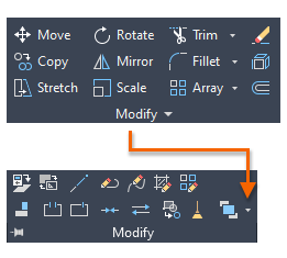
The drop-down list displays options for selected objects plus additional options that apply to all objects of a certain type, such as text.