00:03
Using construction geometry in your models enables you to strategically place a sketch plane,
00:08
axis, or point and specify a location or angle relative to the model.
00:14
Each construction plane is added as a parametric feature in the Timeline,
00:18
which updates automatically when modifications are made.
00:22
Before starting, verify that Capture Design History is enabled.
00:27
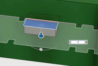
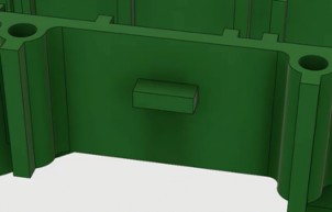
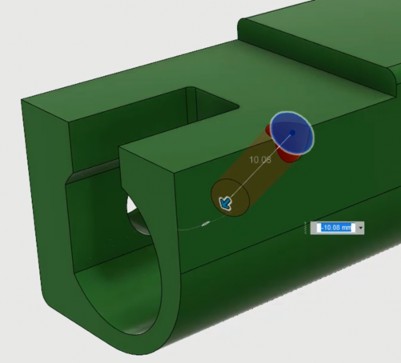
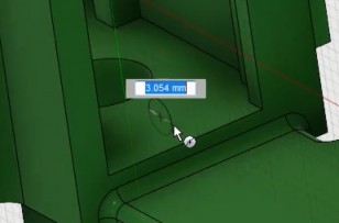
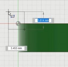
In the first example, to add geometry 8 millimeters down from the top of the model, you can use an offset plane.
00:34
On the Design workspace toolbar, Solid tab, click the Construct menu and select Offset Plane.
00:41
Reference the top face, and then specify the distance to offset.
00:46
Now that the offset plane is created, you can place your sketch on it and use that sketch to generate the desired geometry.
00:53
Notice that a Construction folder is added in the Browser, and the plane is listed under this folder and in the Timeline.
01:01
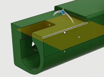
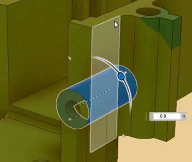
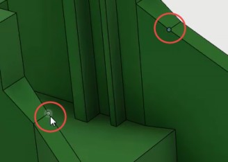
To create a hole at an angle for a set screw to secure the shaft, you can use a plane at angle.
01:07
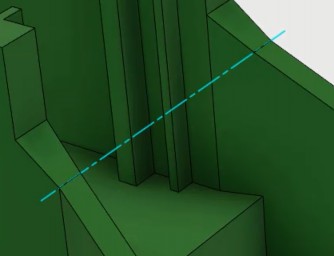
Begin by selecting a line to define the axis for the angle, then drag or type in the desired angle.
01:15
Use the construction plane as a reference for a sketch to add the feature at the specified angle.
01:21
Again, the plane is listed in the Construction folder and in the Timeline.
01:27
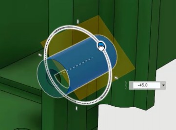
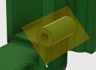
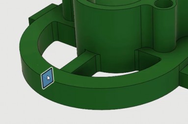
If you want to create a screw hole on a cylindrical face, use a Tangent Plane.
01:32
First, specify the curved face and the angle you want.
01:36
You can also define a reference plane for the angle.
01:39
After creating the plane, resize it by selecting its corners.
01:44
As before, you can use this plane to create geometry.
01:49
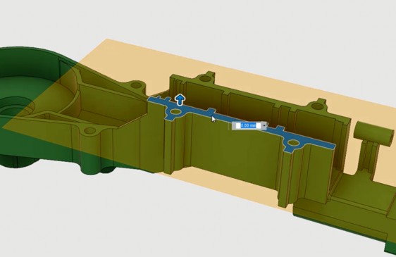
Sometimes, you may need to create geometry from the midpoint of two faces.
01:54
The Midplane tool is perfect for this.
01:57
Specify two planar faces, and the tool generates a construction plane central to those faces.
02:04
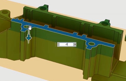
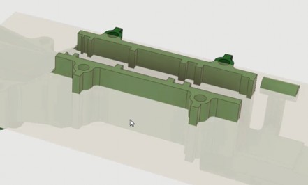
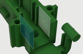
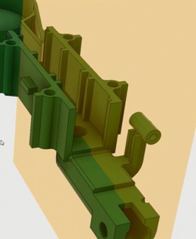
For example, you could use a construction plane between the two faces of a gear housing to add a sketch and define a cut.
02:11
If you later change the location of the construction planes, the features built from them will update parametrically.
02:18
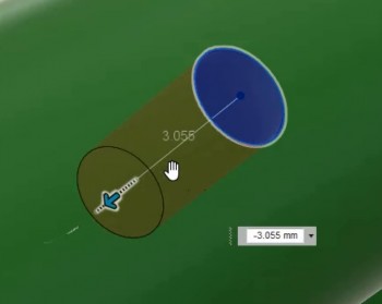
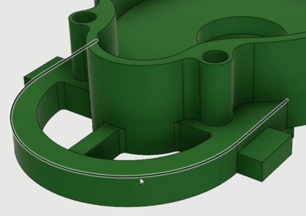
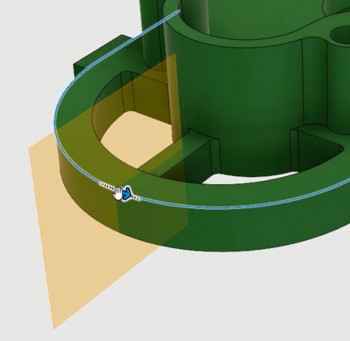
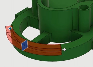
The Plane Along Path tool enables you to create a construction plane at any point along a path.
02:25
Start by specifying the path, and then define a distance ratio from zero to one.
02:31
For instance, entering a ratio of 0.5 places the plane halfway along the path.
02:38
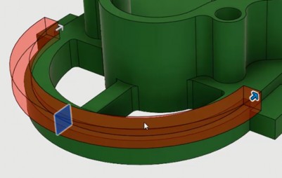
This construction plane can then be used, for example, to sweep a profile along the edge of a housing.
02:46
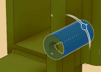
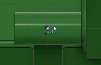
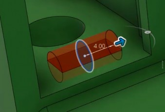
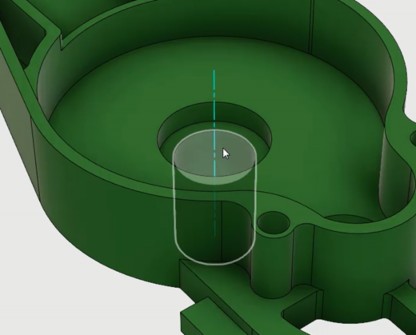
You might sometimes need to create an axis through a cylinder, cone, or torus to use as a reference for other construction geometry.
02:54
Like planes, you can resize an axis after creation.
02:59
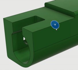
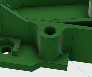
Another option is Axis Perpendicular at Point, where clicking a location generates an axis line perpendicular to that point.
03:08
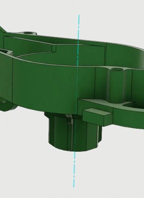
Alternatively, create an Axis Through Two Points, which can be used to define a rotational axis.
03:14
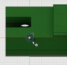
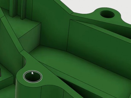
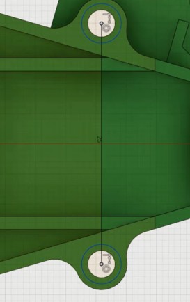
Finally, you can create a point at the center of a circle, sphere, or torus.
03:20
This point serves as a reference for construction or sketch geometries.
03:25
There are additional construction plane, axis, and point tools that can be explored in the Construct menu.


 .
.