00:03
Hello, my name is Thom Tremblay.
00:06
In this course, we'll be taking a look at an overall bridge design workflow.
00:11
And in these lessons, we'll be focusing on how Autodesk Inventor can be used to create custom components,
00:17
to be used in InfraWorks for your bridge designs.
00:21
In this lesson, we'll focus on preparing a pier component for use in InfraWorks.
00:26
We'll focus first on building a component using parameters that are already included in the file.
00:34
When creating complex designs in Inventor,
00:37
it's ideal to include named parameters that tell users and editors down the line what those parameters are being used for.
00:47
You can create these parameters on demand, use sources like spreadsheets to import them in mass, and share them through multiple files.
00:56
Or you can even prepare templates that already include the parameters that you'll need to prepare your model.
01:05
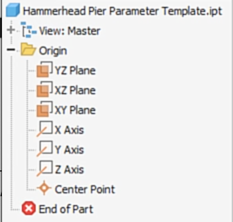
To prepare this model, we're going to start with the Hammerhead Pier Parameter Template.ipt file.
01:12
This is a template that has all of the parameters that you'll need included in it,
01:16
including three parameters that are required by InfraWorks to be able to import a pier.
01:22
Pier height, pier cap left Width, and pier cap right width.
01:28
In addition to being able to open a file that has the parameters,
01:32
you also have the option of using the "Save As" tool to save any file as a template.
01:39
This is a great way to start building up a library of the type of components that you need to create and have them accessible at any time.
01:49
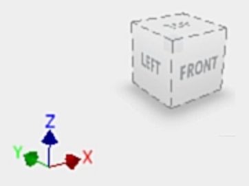
A pier component needs us to create the primary sketches on the xz-plane.
01:54
So, I'll use the view cube to align the xz-plane normal to my screen.
02:00
To make it easier to reference, we can rename this point of view to be front.
02:06
And we can even set up a home view that will make it easier for us to review our work as we go through the process.
02:18
We'll want to expand the origin folder, and turn on the visibility of the planes, axes and center-point there.
02:26
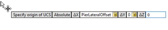
Then we're going to create a UCS.
02:29
A UCS allows us to establish additional coordinate systems within a model.
02:34
These coordinate systems can be related to any other coordinate system and be able to reorient any sketch or feature based on them.
02:43
We'll start the UCS tool and then enter a parameter that's already loaded into the model.
02:50
For that delta x value, we'll use pier lateral offset for this value.
02:56
Then using the Tab key, set the delta y and delta z to zero.
03:02
Right clicking and selecting "Finish", we'll generate the UCS.
03:06
And a double-click of the mouse wheel will zoom all so that we can see our original origin planes and the new UCS that's been created.
03:16
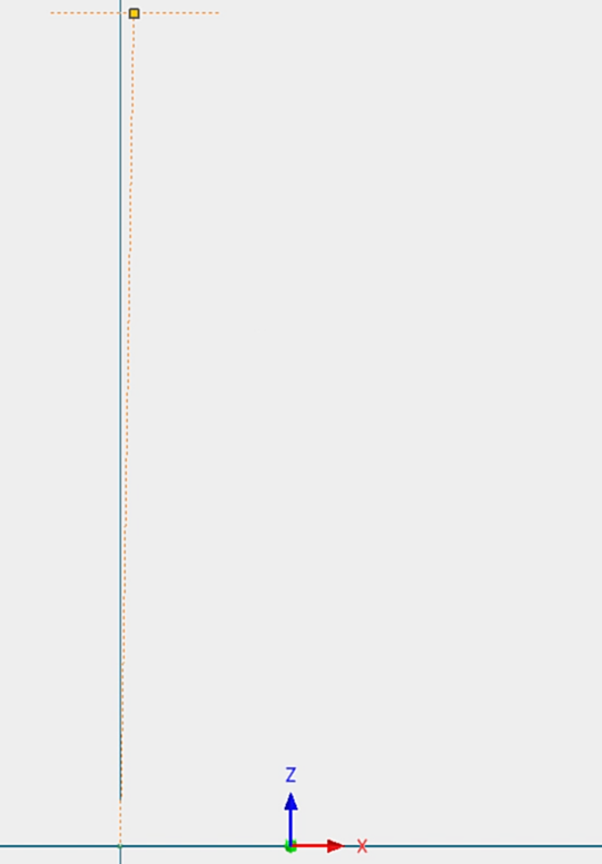
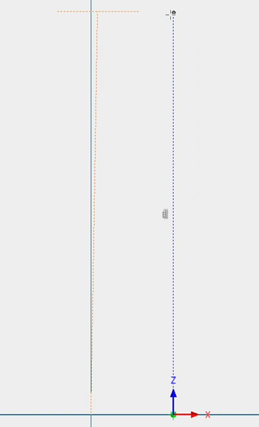
Now, let's create a new sketch based on the model's original xz-plane.
03:23
In this sketch, we'll begin to create construction lines.
03:27
We'll start out with a short horizontal line, well above the origin, that's roughly 20 inches wide.
03:34
Don't worry about centering it immediately,
03:38
because once that's placed, we'll be adding another line from the origin to the midpoint of that horizontal line.
03:46
Next, we'll project the origin center of the UCS that we created and create a vertical line based on that UCS point,
03:55
roughly the same height as the last line we created.
04:00
Then we'll apply a vertical constraint to the line that was drawn from the part of origin to the midpoint of the short line.
04:09
This horizontal line will be used to reference the top of the pier.
04:13
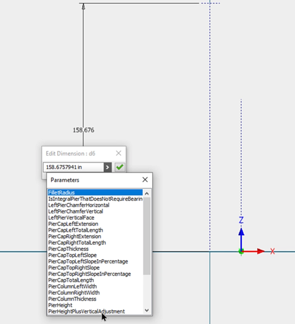
So, we'll establish a dimension from the origin to that line, we'll expand the dialogue,
04:21
select "List Parameters" and choose the pure height plus vertical adjustment parameter for the dimension value.
04:29
With the zoom all, we can see that this is increased to 520 inches.
04:36
We can extend our construction lines to keep them in view as we zoom in.
04:40
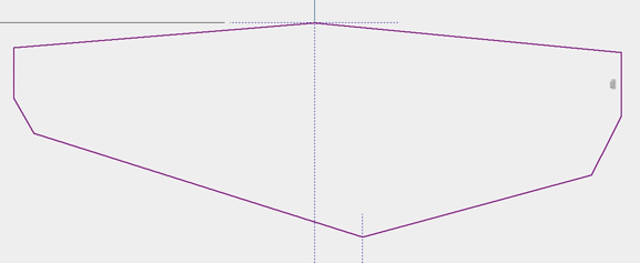
And now we'll begin framing the outline of the pier.
04:44
We'll start the line tool and turn off the construction override.
04:49
Then we'll start a line at the midpoint of the short horizontal line, drawing it down to the left at an angle.
04:56
Then we need a short vertical line, roughly 20 inches.
05:01
A chamfer at an angle.
05:03
And a bottom line that goes to the construction line based on the UCS.
05:10
Then we'll create the same geometry on the other side.
05:15
Because I don't want to lock this into parallel with the vertical line on the left, I'll skew it slightly and then complete the geometry.
05:26
Then we can add a vertical constraint.
05:29
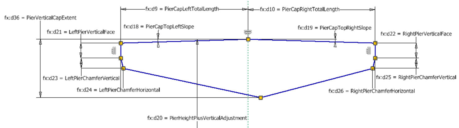
Now it's time to start adding dimensions.
05:32
Again, all of the parameters that we'll need are already built into the part.
05:37
So, as we place dimensions, we can place the angle.
05:43
And we'll just start applying the dimensions.
05:47
So, the first one will be the pier cap top left slope dimension.
05:53
Then we'll use the pier cap right slope.
05:55
And we'll go back and forth between these pairs of dimensions.
06:02
Using the left pier vertical face and its mate on the right side,
06:09
we can use the left pier chamfer vertical, the left pier chamfer horizontal, and then its opposite on the right side as well.
06:20
Now we'll apply the pier vertical cap extent parameter to get the overall height of the cap.
06:27
And then using one of the critical dimensions,
06:29
the pier cap left total length and the pier cap right total length to complete the dimensions of the cap.
06:39
Now we can finish the sketch.
06:42
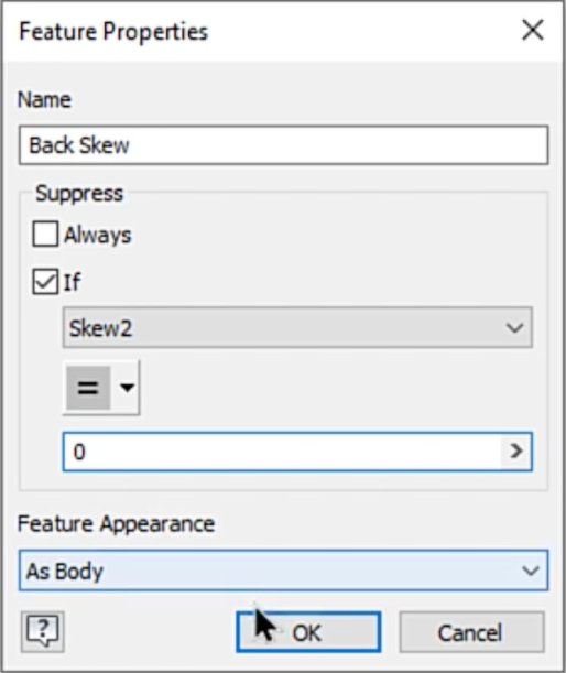
If you want, you can rename your sketch to keep things more manageable.
06:49
And then we'll extrude the cap.
06:53
We'll use the parameter, 'pier cap thickness', to create a symmetrical extrusion.
06:59
This will shut the visibility of the sketch off.
07:03
Now we'll create another new sketch based on xz-plane of the component.
07:08
We'll need to, again, project the origin of the UCS.
07:13
And then draw a line from that origin to the left, using the pier column left width parameter.
07:19
Note that we can type in the names of the parameters, rather than using list parameter.
07:26
And I'll draw another to the right, using the peer column right width value.
07:32
Drawing a vertical line, we can gesture over the bottom edge of the cap to project that bottom edge into the sketch.
07:41
We'll do it for the right and then for the left.
07:45
To close off the sketch, we'll draw two lines from the vertical lines we've drawn down to the bottom point of the cap.
07:53
And back up to the vertical line.
07:58
We can then extrude using, again, the symmetry to create our column using the pier column thickness parameter.
08:08
And then apply a fillet to the bottom edge of each side, using the fillet radius parameter for the value.
08:17
In the next lesson, we'll be exercising the model to make sure that the parameters perform the way we need them to.