Try it: Road Design Editing in Civil 3D
- In the Present/Share ribbon > Share panel select the Export to IMX tool.
- Select the Use Entire Model option.
- Check the Target Coordinate System is still set to CANBC-TCN.
- In the Target File(s) field click the folder icon, then browse to a location that will be easy to find later.
- Open Civil 3D.
- In the Toolspace > Prospector tab scroll down to the Data Shortcuts
- Right-click on Data Shortcuts and select Set Working Folder.
- Make sure the C:\Civil3DProjects folder is selected.
- Right-click on Data Shortcuts again and select new Data Shortcut Project folder.
- Give the project folder the name of Park Bridge Project and click OK.
- Save the file that opened with Civil 3D to the C:\Civil3DProjects\Park Bridge Project folder, named From Infraworks Import.
- In the InfraWorks ribbon > Import panel select Import IMX.
- Browse to the location of the exported IMX file. Select it and click Open.
- Select one of the polylines that represent a waterway, right-click and choose Select Similar.
- Delete the selected polylines. You may also want to delete alignments that are not involved in your design. These will vary depending on what was in your project area at the time of the IMX Export.
- Select the Existing Ground and in the context ribbon > Modify panel select Surface Properties.
- In the Surface Properties Information tab change the Surface Style to Border only. Click OK.
- In the drawing file select the alignment for the Park Bridge Road (it will be under the corridor making it difficult to select). Right-click and choose Alignment Properties.
- In the Information tab change the name to Park Bridge Road. Close the Alignment Properties dialog.
- In the Toolspace > Prospector tab > expand the Alignments > expand Park Bridge Road > expand Profiles.
- Right click on the profile name and choose Properties.
- In the Information tab change the name to Park Bridge Road. Close the Properties dialog.
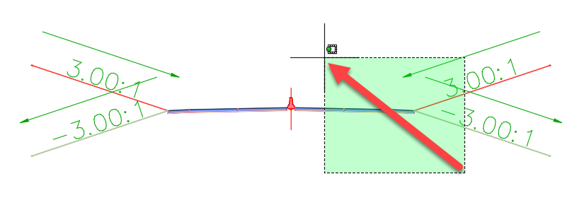
- In the Toolspace > Prospector tab > expand the Assemblies area. Right-click on any named assembly (not “unassigned”) and choose Zoom to.
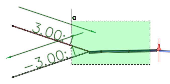
- Use a crossing window select to select the right two lanes, shoulder and daylight.
- Right-click and choose Move To from the right-click menu. This is NOT the AutoCAD MOVE command, but a specialized command for working with subassemblies.
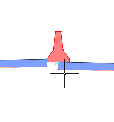
- Select on the assembly marker to center the right side under the jersey barrier.
- Repeat the crossing window selection for the left side, right-click and choose Move To and select the assembly marker.
- In the Home ribbon > Palettes panel select the Tool Palettes icon.
- In the tool palette switch to the Lanes tab.
- Select the LaneSuperelevationAOR subassembly.
- In the Properties palette > Advanced Parameters area change the following parameters:
- Pave1Depth: .33
- Pave2Depth: 0
- Base Depth: .5
- Potential Pivot: no
- In the drafting area right-click and choose Replace.
- Select one of the lanes that is already attached to the assembly. Hit <ENTER> to end that specific placement. The Replace Subassembly command will still be running for use in the next step.
- Select another of the already existing lanes and hit <ENTER>.
- Repeat this for the other two lanes. Hit <ENTER> twice to end this series of placements.
- In the tool palette > Lanes tab select the LaneSuperelevationAOR again.
- In the Properties palette > Advanced Parameters area change the following parameters:
- Width: 5
- Pave1Depth: .33
- Pave2Depth: 0
- Base Depth: .5
- Potential Pivot: no
- In the drafting area right-click and choose Replace.
- Select one of the shoulder subassemblies that are already attached to the assembly. Hit <ENTER> to end that placement.
- Select the other of the already existing shoulders and hit <ENTER>.
- Hit <ENTER> twice to end those placements.
- Close the Properties palette and the tool palette.
- In the Toolspace > Prospector tab expand Corridors, right-click the corridor name and choose Properties.
- In the Information tab change the corridor name to Park Bridge Road.
- In the Parameters tab select the Set All Targets button.
- For the Surfaces area click in the field that reads Click Here to Set All.
- Select AIW_Existing_Ground. Click OK twice.
- Scroll to the right to the target column and select the ellipsis button for the second (middle) region Target.
- For the Surface area click in the field that reads Click her to set all.
- Select the <none> option and click OK twice.
- Click OK in the corridor properties and select Rebuild the Corridor when prompted.
- Close the Panorama palette if it opens.
- Save the file.
- In the Toolspace > Prospector tab right-click on Data Shortcuts and choose Create Data Shortcuts.
- Select the AIW_Exisitng_Ground surface
- Select Park Bridge Road alignment. Select the Park Bridge profile but deselect all others.
- Select the Park Bridge Road corridor.


