00:04
Now, I'm going to talk about the Civil 3D object.
00:08
In Civil 3D, we have six types of objects we can put in what we call DREF, data references.
00:15
So it's like external references put together, but now it's about the Civil 3D object.
00:21
So here in this table, you see the Surface, Alignment and Profile, the Pipe network, the Corridor.
00:28
These four elements obviously is the object, is the intelligent objects to make your infrastructure project.
00:34
And the tool has one sample lines, and view frame groups are used to create your 2D plans, cross-section, and plan and profile views.
00:42
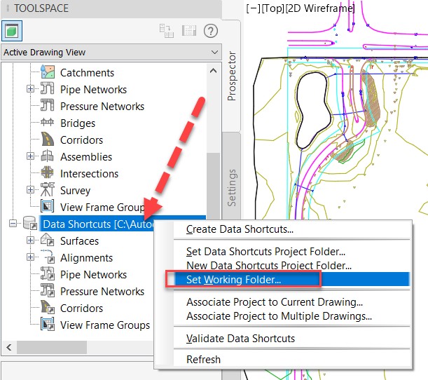
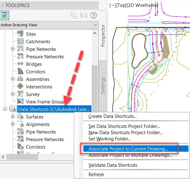
So, to use this DREF, there is a certain series of steps to do.
00:47
Again, is to set up a working folder associates the Data Shortcut project to your drawing and then save the file.
00:55
So, for example, now I can delete my label of my previous example.
01:02
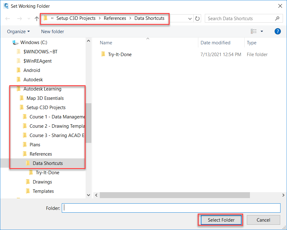
And what I can do is I will create a new working folder.
01:10
So, for example, I will create a new one, and I said, working folder.
01:25
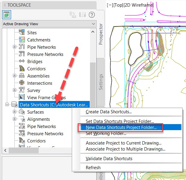
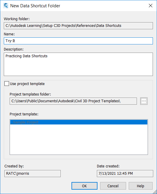
Then I create a new Data Shortcut project folder in this working folder.
01:32
It's possible to have different project folder inside the working folder.
01:36
You can have one, two, three, several, doesn't really matter.
01:40
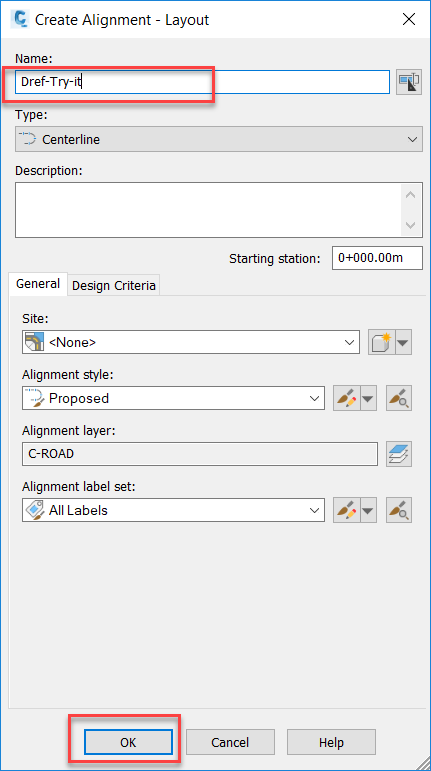
So, for example, I would say Live-demo.
01:50
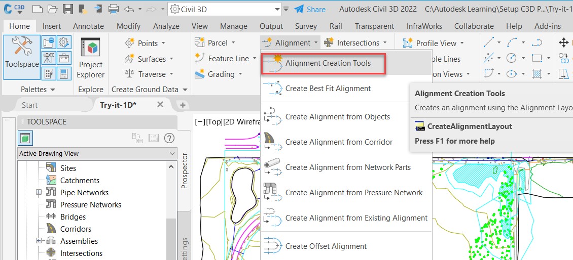
Then for example, I will create an alignment, which is a Civil 3D object.
02:00
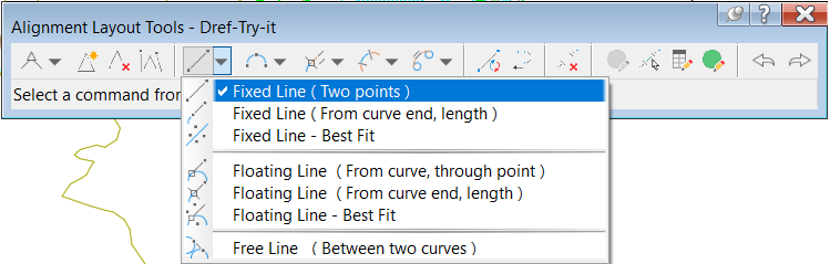
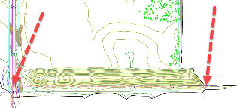
So, I will use just a tangent like this to represent my main road, for example.
02:12
Here is my alignment.
02:13
You see so far, I have nothing.
02:15
Why? Because I didn't add any reference.
02:19
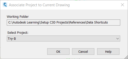
So first, what I need to do is, like, I save my file so somewhere, then I associate my current drawing to the project, so Data Shortcut project.
02:35
And you see, this is the one I just created.
02:39
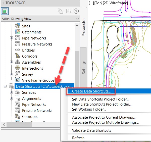
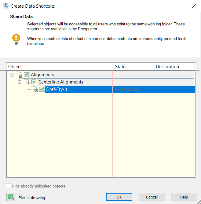
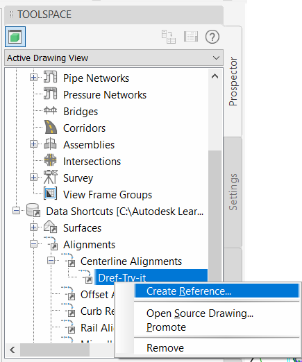
And now, I will be able to create a Data Shortcut.
02:42
So, for example, here, obviously, I will add this element I just created.
02:50
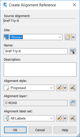
And if I open a new file, I will be able to insert automatically this alignment.
03:05
So, this is a basic example that if I want to show you, I would say with on a real project, this is what we normally do.
03:14
We have the surface.
03:18
And I call in reference my alignment.
03:21
As you can see here, I have no icon.
03:23
But I have this icon, arrow.
03:26
What that means that means that come from this reference. Okay.
03:32
And the thing is, you try to split as much as you can with data by using the Data Shortcut.
03:37
So, for example, in this file, I only have my surface, and I call my alignment as a reference.
03:43
And how to know it is a reference, I can see this arrow icon things that I see here.
03:49
So, my alignments come from this Data Shortcut.
03:54
And if I do the same steps, for example, here I have my surface in reference, and I have my alignment, which is in my file.
04:04
And I do the same, for example, for the pipe network.
04:07
My pipe network is here, as you can see in blue.
04:12
And I called in reference My surface.
04:16
And I do that also for the corridor.
04:19
So why do I do this?
04:21
Is because in AutoCAD and Civil 3D is not possible to open the same file with several users with several members of the project.
04:31
So, if you work in a complex and large project, you want all your colleagues to work.
04:36
And for example, here one person can be in charge to design to model the surface,
04:42
one other person can be in charge to design the alignment, and another for the pipe network, etcetera.
04:48
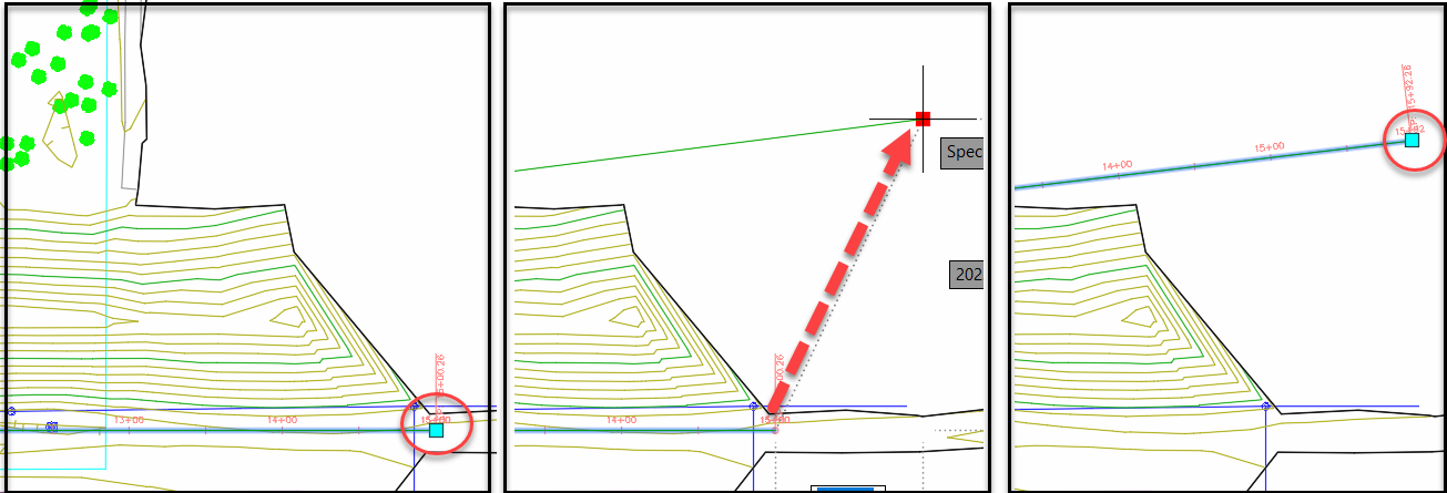
And the greatest thing here is, for example, if I take my surface and I do a modification in my surface, for example, here, I will add a grading.
05:03
You see, it's modified.
05:05
I need, first, to save my file.
05:15
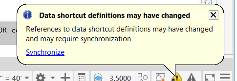
And here for the person who will be in charge to design the Alignment, he will see this pop up hey, my reference has been updated.
05:23
I need to synchronize.
05:25
And then you give a bit of time to see if you need to see to work.
05:28
And you see here I could see the modification of my colleague.
05:32
And this is a way to enhance the collaboration because if you put all the data in one side, first it will be heavy, long to open.
05:40
And the second point is only one person will be able to work on your project.
05:44
That's why if you are able to speed your data.
05:47
It's always better for the collaboration.
05:50
And obviously, at the end, if you follow the same workflow.
05:53
Okay, so I added in reference my surface.
05:55
I added reference my alignment, my corridor.
05:58
You can have this result where you have your 2D deliveries.
06:04
So, for example, here is just a layout, and I can show you.
06:09
So, I have this layout where you can see my plan view and my profile view.
06:14
So, this is a PDF coming from this file.
06:17
As you can see, I have my plan view of my corridor, my path network.
06:20
I have here my profile view of my pipe network.
06:24
And I will be also able to do some cross section.
06:28
Also, it's not the topic of today, but that would be easy also with the references to insert that in your InfraWorks model.
06:37
And for example, here, if I change a bit the settings,
06:44
you can see that is exactly obviously is the project of my Civil 3D model with my path network and my corridor.
06:51
So that's what I wanted to show you that InfraWorks may be complicated, but this is how you work.
06:57
As I said in the working folder, you can attach different Data Shortcut project.
07:02
So, to know which one you are, obviously try to read the rest ones.
07:06
The Data Shortcut enhance the collaboration because you can insert copies of references.
07:13
One thing to know the objects you insert as references cannot be modified.
07:18
The objects can only be modified in the source drawing.
07:21
So, it's better for a choice.
07:24
Obviously, you will be able to change the size of the objects.
07:27
That's something I will explain that later.
07:29
And again, the lesson is if your colleague modify a Civil 3D object and save the file,
07:35
you will be able to see the pop-up asking you to synchronize the references.
07:40
Things to know when you use the data references there are a lot of benefit, but you have to use it carefully.
07:47
The first thing is if you delete a reference that can take time to delete it,
07:51
because in Civil 3D project, the object the most important is the surface.
07:56
Why? Because you design your alignment and profile based on the surface.
08:01
The corridor is designed based on the surface.
08:03
So, we can easily imagine that if you delete the surface, that will take a lot of time because all the elements have an interaction to each other.
08:11
The second point is don't exceed 128 characters for the name and the path location.
08:17
Otherwise, you will have a potential risk.
08:20
The third one is a recommendation.
08:22
Do not change the names and the locations of the references.
08:26
Obviously, the software will always point to the file, but if you change the name of the files, Civil 3D will not be able to recognize it.
08:33
So, it's a recommendation, but for a certain reason by experience, you will have to do that in certain project.
08:39
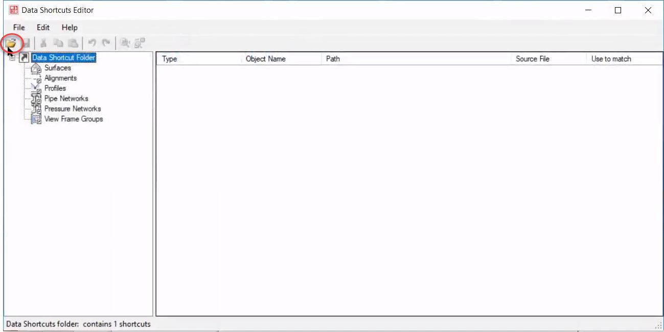
So, if you need to change the names, I advise you to use a tool Data Shortcut Editor.
08:45
I going to do a demo again.
08:47
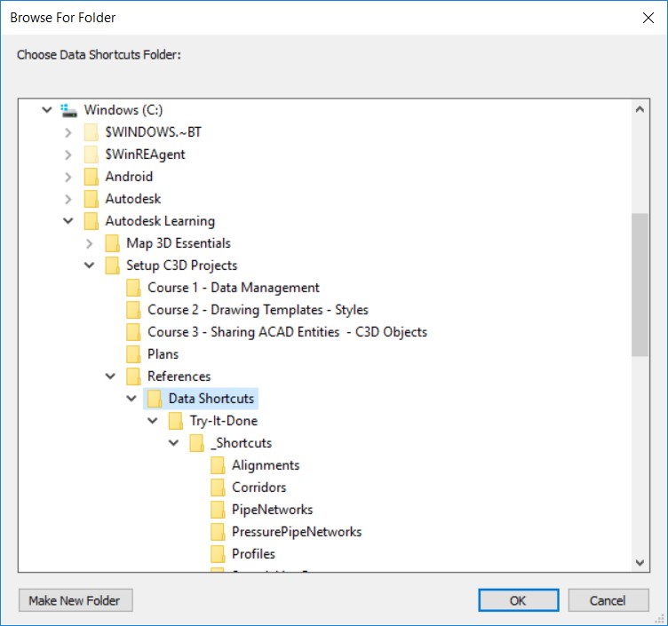
I go to Data Shortcut Editor.
08:52
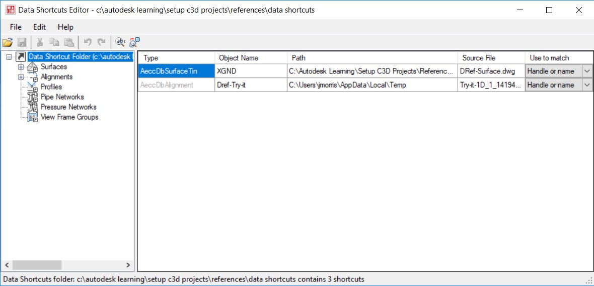
I open, obviously, the file I want, then I select my Working Folder.
09:01
And here, as you can see, I have all my references.
09:06
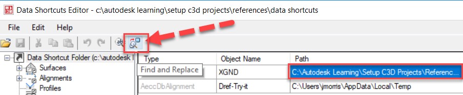
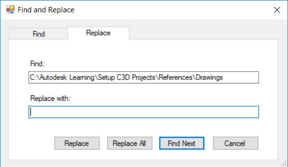
And the good thing is, like the reference manager, I can change and find and replace.
09:12
So that applies for the object name but also, for the best location.