Step-by-step:
You can define pipes in a model to be open or closed, and whether or not they contain check valves to allow only a unidirectional flow.
- Open the appropriate .aprx file in ArcGIS Pro.
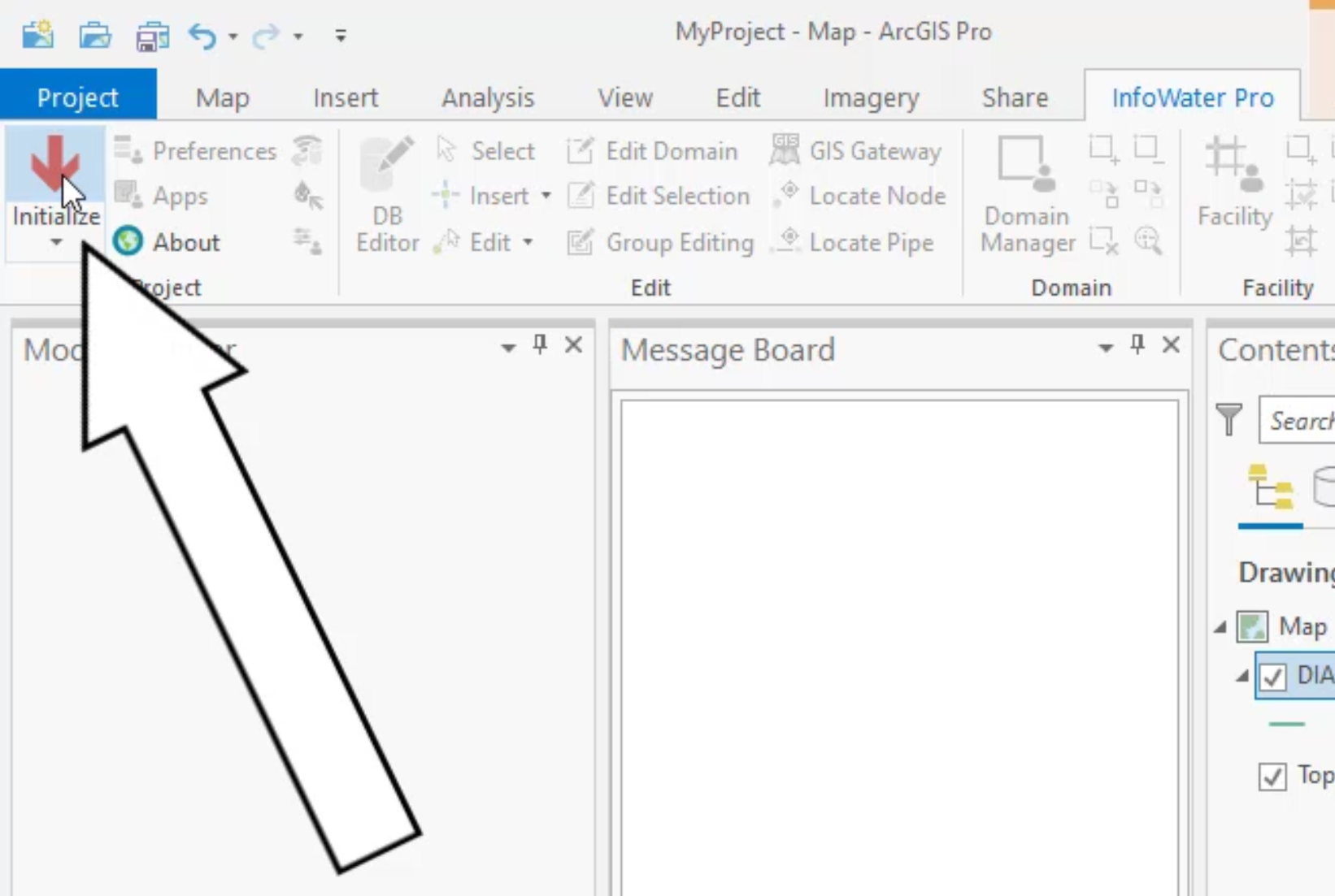
- From the ribbon, InfoWater Pro tab, click Initialize.
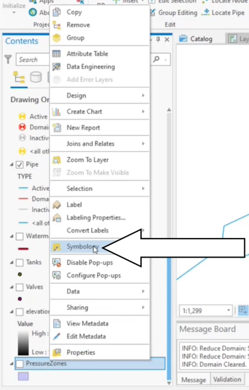
- From the Contents pane, right-click PressureZones and select Symbology.
- In the Symbology pane, expand Primary symbology and select Unique Values.

- In the Symbology – PressureZones panel, expand the Field 1 drop-down and select ZONE.
- Note the four colors that represent the four pressure zones.

- Zoom out and pan the model to view all four zones.
- Locate the 3 locations where the system connects pressure zones 2 and 3.

The very north has a pressure reducing valve, or PRV, that reduces the pressure as flow goes from zone 3 to zone 2. The other locations have open pipes connecting the pressure zones. These pipes either need check valves, or they need to be closed to prevent water from rushing out of zone 3.
- On the InfoWater Pro ribbon, Edit panel, click Select.
- In the model, zoom into pipe 8285.
- Draw a selection window around pipe 8285.

- In the Model Explorer, Attribute tab, expand the Tools drop-down and select Initial Status.

- In the Pipe Initial Status dialog box, set Initial Status Options to Closed.
- Click Create.

- In the model, select pipe 12415.
- In the Model Explorer, set Check Valve to Yes.

- From the Model Explorer toolbar, click Save.
Once you have finished assigning check valves to the pipes, it is good practice (though, not required) to run a special query and verify the changes you just made.
- On the ArcGIS Pro ribbon, Map tab, Navigate panel, click Full Extent.

- On the InfoWater Pro ribbon, Domain panel, click Domain Manager.
- In the Domain Manager dialog box, select Special Query.
- In the Special Query drop-downs, select Pipes and Check Valves.
- Click Add.

- In the model, locate pipe 12415 and notice that it is highlighted.
- To remove the query, in the Domain Manager, click Remove.

- In the Special Query drop-downs, select Pipes and Initially Closed.
- Click Add.
- In the model, locate pipe 8285 and notice that it is highlighted.
- In the Domain Manager, click Remove.
- Close the Domain Manager.


