Step-by-step:
To run a steady state analysis, you must first set boundary conditions, such as pump status or tank levels. In this exercise, you define pump operations and assign an initial level to the tank. Note that a steady state analysis has already been created.
- Open the appropriate .aprx file in ArcGIS Pro.
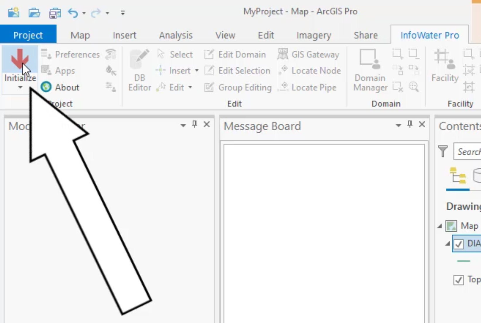
- From the ribbon, InfoWater Pro tab, click Initialize.
- In the model, locate tank TD5004.
- From the InfoWater Pro ribbon, Edit panel, click Select.

- In the model, draw a selection window around tank T5004.

TIP: If you are having trouble finding this tank in the model, use the Model Explorer to locate it. In the Attribute tab, enter T5004 in the name field, press ENTER, and then click Zoom to an Active Element.
- In the Model Explorer, Attribute tab, set Initial Level to 120.

Tank T5004 will now have a hydraulic grade line, or HGL, of 120 feet above the ground surface during the steady state analysis.
- In the model, locate tank T5000 and select it.
- In the Model Explorer, Attribute tab, set Initial Level to 90.
Tank T5000 will now have an HGL of 90 feet above the ground surface during the steady state analysis.
- In the model, locate treatment plant WTP100 and select it.
- In the Model Explorer, Attribute tab, set Head to 5880.
Treatment plant WTP100 will now operate at a constant HGL of 5880 feet during the steady state analysis.
- On the InfoWater Pro ribbon, Domain panel, select Enlarge Domain.

- In the model, select pumps P-100 and P-120.

- On the InfoWater Pro ribbon, Domain panel, click Reduce Domain.

- In the model, select the pipes adjacent to pumps P-100 and P-120.

Note that only the pumps should be selected.
- On the InfoWater Pro ribbon, Edit panel, select Group Editing.

- In the Group Editing dialog box, select Pump/Valve Status.
- Set Initial Status to Closed.
- Click Apply.
- Click OK.

- Close the Group Editing dialog box.
- On the InfoWater Pro ribbon, Domain panel, click Clear Domain.

The pumps and tank are now configured and ready for the steady state analysis.


