Create a simple floor plan using AutoCAD LT
Follow these steps to draw external walls, internal walls, and windows.
In this tutorial, you will learn how to create a simple floor plan. This will allow you to conceptualize and communicate the overhead dimensions and layouts of your designs.
Prerequisites
If you haven't already, learn these commands before taking the tutorial:
Draw external walls
- New drawing. In Start Drawing templates, click on the New button in the top toolbar and select the Tutorial i-Arch template.
- Mspace. In the new drawing, you start out in the paper space. Click Paper in the status bar at the bottom of the screen to switch the model space. In the model space, a UCS icon
 displays instead of a triangle.
- Rectang. In the ribbon, click the Home tab. In the Draw panel, click Rectangle.
 Specify the lower left and upper right points of the rectangle with your mouse to form the outside of the exterior wall.
 - Offset. In the Modify panel, click Offset.
 Specify 9" by typing 9 and pressing Enter. Select the rectangle.
 - Specify an inside point to create the other side of the wall. Then, hit Enter to escape the Offset command.

Draw internal walls
- There is no double-line tool on the ribbon, so enter DLINE and press Enter to start the command.
- Type w and press space for the Width option. Enter 4 to specify a width of 4" for the interior walls.
- Right-click and select Osnap Overrides, then select Nearest.
- Click to specify a point on the inside rectangle of the wall on the East side.

- Click to specify a point inside the building.
- Right-click and select Osnap Overrides, then select Perpendicular.
- Click on the inside of the South outer wall. Press Enter to escape the dline command.

Note: The dline command is available only in AutoCAD LT. If you are following these steps in AutoCAD, use mline instead.
Draw a simple window
- Osnap. Click the small down arrow for the object snap menu in the status bar.
 Click on Midpoint, Nearest, and Perpendicular to enable these modes.
- Line. In the ribbon, click Line. Draw a small 9" line through the outer wall on the East side.

- Copy. Select the line you just created. In the ribbon, click Copy.
 For the base point, click on the selected line.
 - Displacement. Move your mouse to specify a direction along the wall, but do not click. Type in 48 and press Enter.

- Glass pane. In the ribbon, click Line. Click to specify the Midpoint of one of the lines you created, then click to specify the Midpoint of the second line.

- Press Esc to stop the line command. Your simple window is complete.

Dimension the window
- Dimension. In the ribbon, in the Annotation pane, click Dimension.

- Place the dimension. Specify both sides of the window by clicking on the outside edges with your mouse, then dragging away from the wall.

Conclusion
In this tutorial, you learned how to create a simple floor plan in AutoCAD LT.
Now you can:
- Draw external walls
- Draw internal walls
- Draw a simple window
- Annotate with Dimensions
In this tutorial, you will learn how to insert and scale a plumbing fixture in a sample drawing. This will allow you to customize templated fixtures to your desired specifications.
Open
- Select Explore Sample Drawings from the start tab.
- Click on Sheet Sets > Architectural > Res > Wall Base.dwg and open the file.
- You will be asked if you want to open the drawing in Read-Only mode. You will not need to save changes, so click Yes.
- Zoom in to room 205.

Insert
- In the ribbon, click on the Insert tab. In the Block pane, click Insert.

- In the Blocks palette, Current Drawing tab, scroll down and click the Sink-Single icon.

Scale
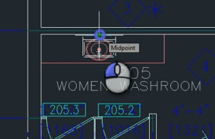
- Press S for Scale and enter 0.75 to scale the sink to ¾ of its original size.
- Use the Midpoint object snap to place the sink on the midpoint on the front of the splashboard.
Assign properties
- Select the oval sink. Right-click and select Properties to find out which layer is assigned to it. The sink’s layer, 2_Arch_Plan_Sink, will be specified in the Layer row of the Properties palette, underneath General. Press Esc to deselect.
- Select the new sink that you just placed.
- Right-click and select Properties in the menu.
- In the General section of the Properties palette, select 2_Arch_Plan_Sink from the drop-down menu located to the right of the Layer row.
Erase
Select the old sink and erase it by clicking Erase from the ribbon or by pressing the Delete key.
Conclusion
In this tutorial, you learned how to insert a plumbing fixture.
Now you can:
- Open a sample drawing
- Insert a fixture
- Assign layers