Create and edit electrical circuits
Identify, create, and edit electrical circuits.
Step-by-step guide
Identify, create, and edit electrical circuits.
- Open the Revit project file E01_01.rvt.
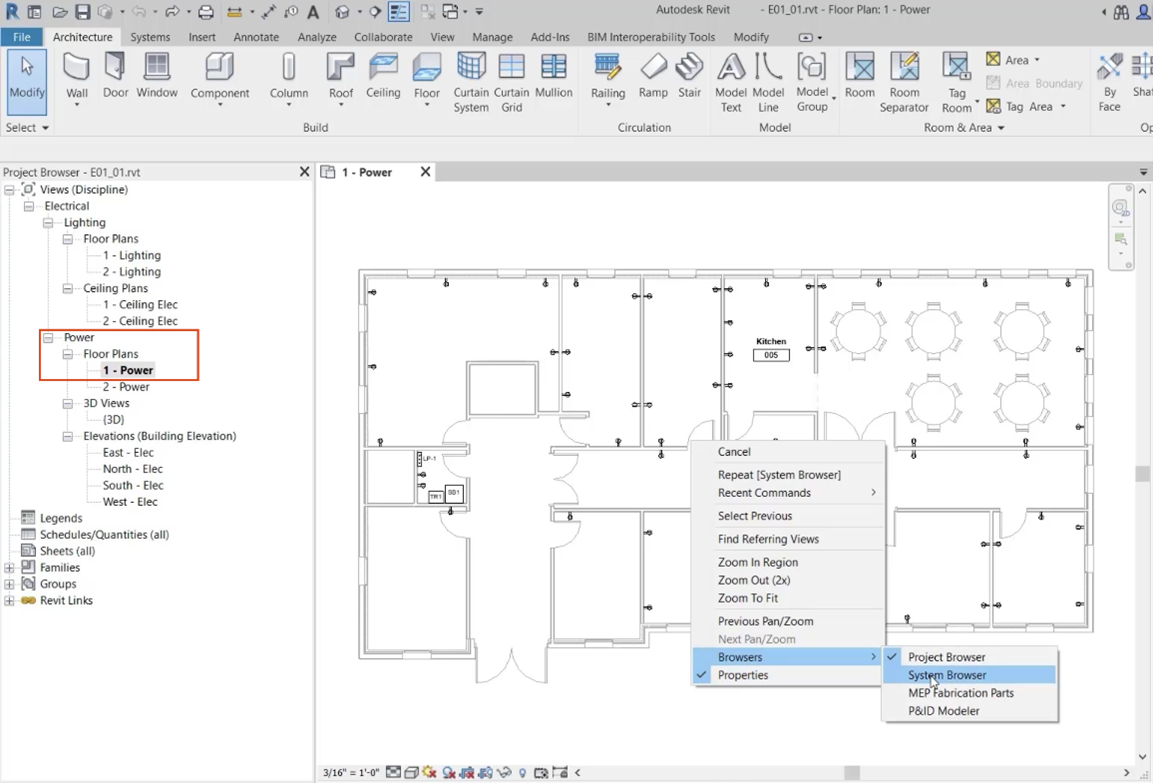
- In the Project Browser, set the current view to Power > Floor Plans > 1 – Power.
To check the project for unassigned elements:
- Right-click in the drawing area and choose Browsers > System Browser.
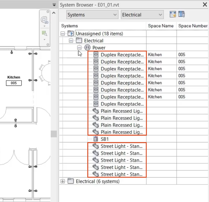
- In the System Browser, expand the Unassigned branch.
- Expand Electrical.
- Expand Power.
The receptacles and lighting fixtures under Power need to be assigned to a circuit.
To assign the duplex receptacles to a circuit:
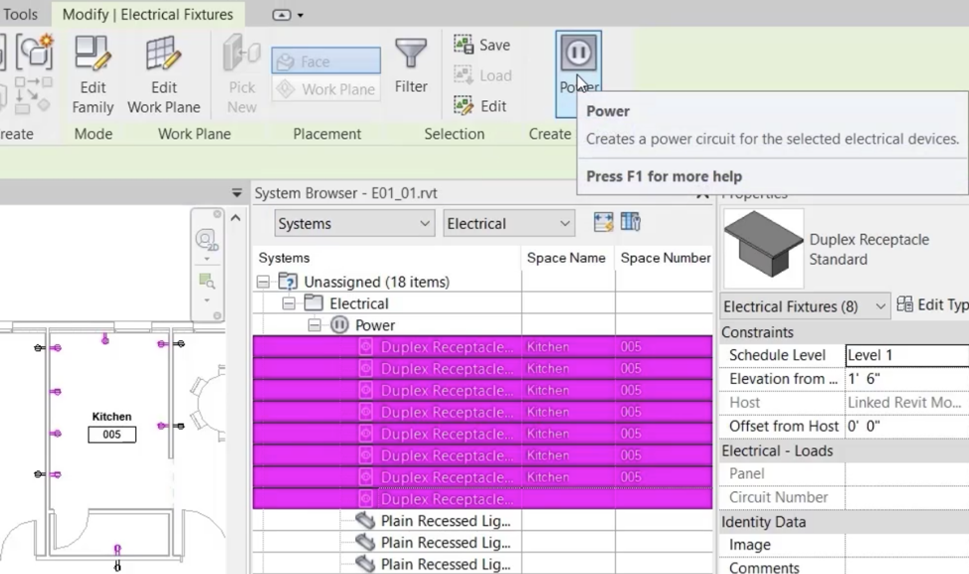
- In the System Browser, select the 8 Duplex Receptacles.
The receptacles appear highlighted in the kitchen area of the floor plan, and the ribbon switches to the Modify | Electrical Fixtures contextual tab.
- From the ribbon, Create Systems panel, click Power.
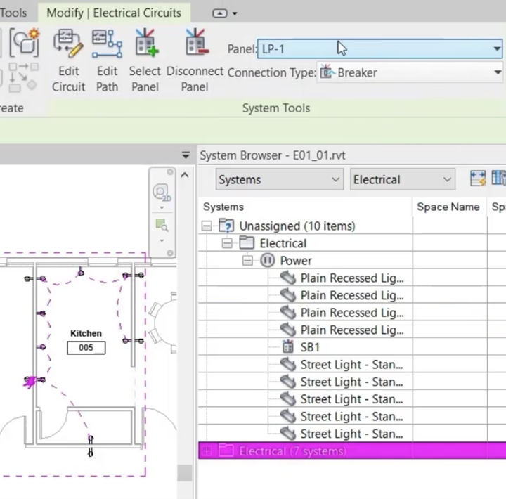
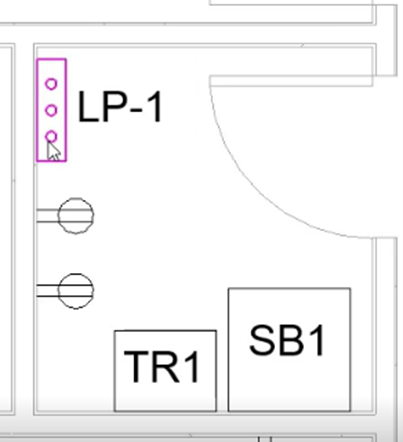
- Expand the Panel drop-down and select LP-1 as the panel for the circuit.
The receptacles no longer appear in the System Browser as unassigned, and in the floor plan, the receptacles now appear connected.
The System Browser shows that some of the lighting fixtures are also unassigned.
- From the Project Browser, open the view Lighting > Floor Plans > 1 – Lighting.
- In the System Browser, select the four Plain Recessed Lighting Fixtures.
The lighting fixtures appear highlighted in the lower-right room of the floor plan.
- Press ESC to clear the selection.
To add the four plain recessed lighting fixtures to an existing circuit:
- From the room to the left of the four fixtures, select a lighting fixture.
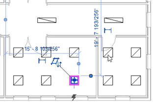
- In the ribbon, Electrical Circuits tab, System Tools panel, click Edit Circuit.
- From the ribbon, Edit Circuit panel, click Add to Circuit.
- In the lower-right room of the floor plan, pick one of the four unassigned plain recessed lighting fixtures.
A warning message indicates that 80% of the defined rating has been exceeded for the circuit.
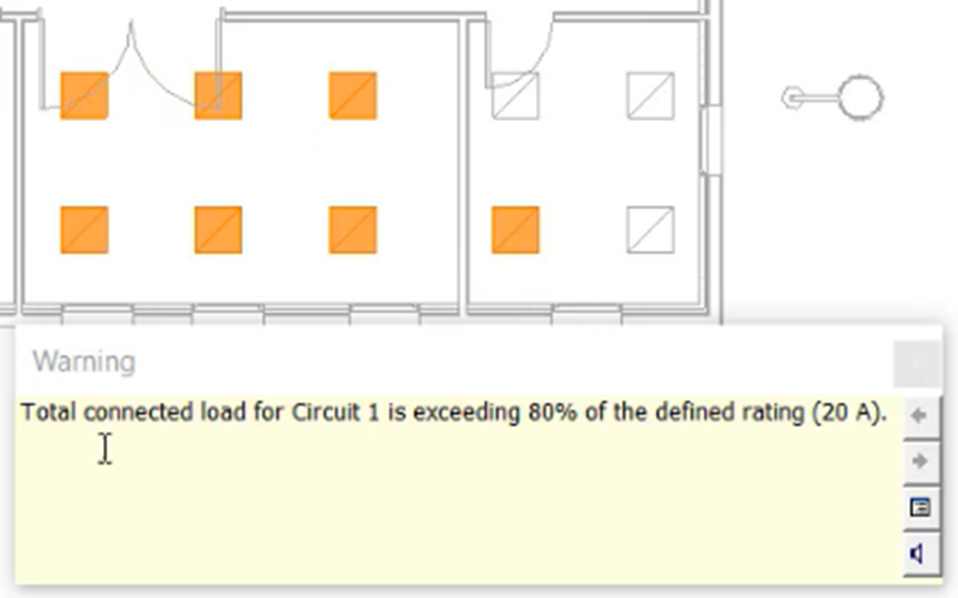
- Close the warning message.
- From the ribbon, Mode panel, click Cancel Editing Circuit.
In this case, create a new circuit:
- From the floor plan, select the four unassigned lighting fixtures.
- Repeat steps 8 and 9 to create a circuit connected to LP-1.
- With the new circuit still highlighted, in the ribbon, click Edit Circuit.
Now, move the 12 lighting fixtures in the two rooms to the left over to the newly created circuit:
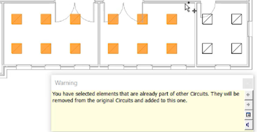
- From the ribbon, click Add to Circuit.
- Click the drawing area and drag to draw a selection box around the 12 lighting fixtures.
- Review and Close the warning message.
- In the ribbon, click Finish Editing Circuit.
Back in the System Browser, the final items that need to be connected to a circuit are the lights for the parking lot. To create another circuit:
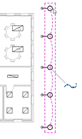
- On the right side of the drawing area, click in the parking lot and drag to select the five Street Light fixtures.
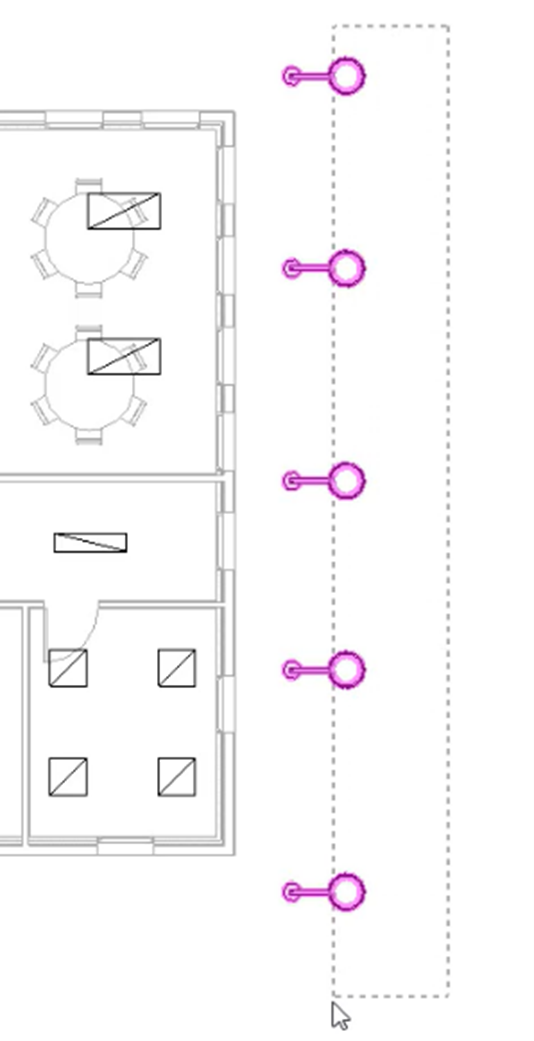
- Repeat steps 8 and 9 to connect the new circuit to LP-1.
The warning message indicates there are not enough slots on LP-1 for this circuit.
- Click Cancel to close the window.
To view the Properties for LP-1:
- Switch the view to 1 – Power.
- Zoom into the view and select panel board LP-1.
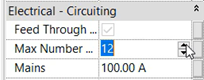
Note that the maximum number of single pole breakers is currently set to 6.
- Increase the Max Number to 12.
The exterior lighting can now be connected to LP-1.
- Return to the view 1 – Lighting.
- Position your cursor over a lighting fixture and press the TAB key to highlight the circuit.
- Click to select the circuit.
- From the ribbon, expand the Panel drop-down and select LP-1.
To review the rating for the new circuit:
- Repeat steps 33-34 to select the circuit.
- In the Properties panel, scroll down to see a Rating of 20A.
- Press ESC to deselect the circuit.
To access the electrical settings for this project:
- Type “ES” to open the Electrical Settings window, where the default circuit rating for all new circuits is set at 20A.
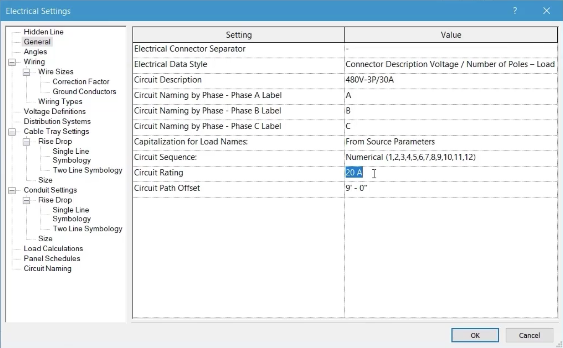
- Close the Electrical Settings window.
To change the rating of the parking lot circuit:
- Repeat steps 33-34 to select the exterior lighting circuit.
- From Properties, set the circuit rating to 30A.
![]()
- Press ESC to deselect the circuit.
A final review of the System Browser shows that there are no unassigned receptacles or lighting fixtures in the project.
- Save the project.