& Construction

Integrated BIM tools, including Revit, AutoCAD, and Civil 3D
& Manufacturing

Professional CAD/CAM tools built on Inventor and AutoCAD

Integrated BIM tools, including Revit, AutoCAD, and Civil 3D

Professional CAD/CAM tools built on Inventor and AutoCAD
Build an InfoDrainage model using Inflows, Junctions, Stormwater Controls, and Connections.
Type:
Tutorial
Length:
3 min.
Tutorial resources
These downloadable resources will be used to complete this tutorial:
It is very easy to add predefined storm drainage system objects into your surface model using the tools in the Toolbox. Best practice is to add the individual junction objects, such as manholes, and then connect them with pipe or channel objects.
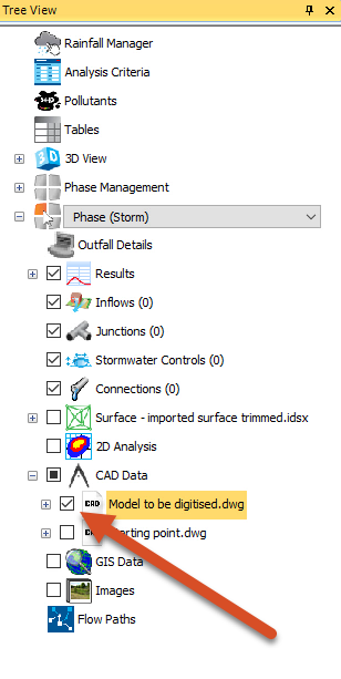
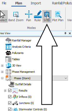
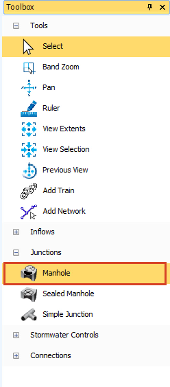
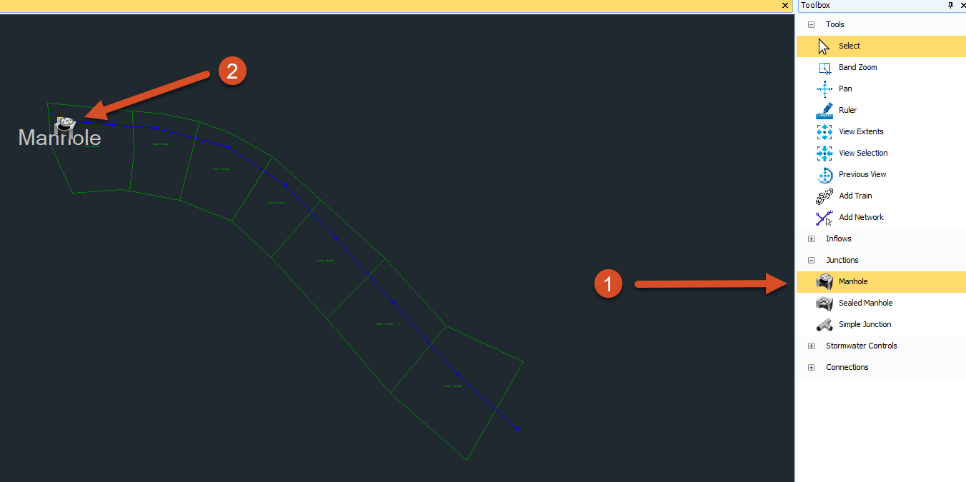
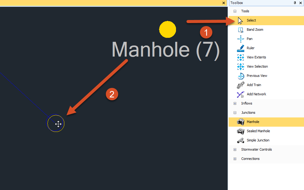
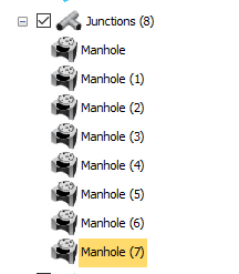
In the Tree View, the manholes were added under the Junctions node in numerical order. You can rename them by right-clicking on the name and then choosing Rename.
Industry:
Role:
How to buy
Privacy | Do not sell or share my personal information | Cookie preferences | Report noncompliance | Terms of use | Legal | © 2025 Autodesk Inc. All rights reserved
Sign in for the best experience
Save your progress
Get access to courses
Receive personalized recommendations
May we collect and use your data?
Learn more about the Third Party Services we use and our Privacy Statement.May we collect and use your data to tailor your experience?
Explore the benefits of a customized experience by managing your privacy settings for this site or visit our Privacy Statement to learn more about your options.