Creating a 2D initial condition zone
Specify initial conditions within a 2D zone in preparation for running a simulation.
Tutorial resources
These downloadable resources will be used to complete this tutorial:
Step-by-step guide
A 2D zone does not go through the same initialization process as a 1D model, and there is no connection between the 1D and 2D engines during initialization. Therefore, it is necessary to specify initial conditions within the 2D zone to prevent surges of water occurring when the simulation starts.
The initial conditions 2D object is used to assign initial hydraulic, infiltration, and water quality values to 2D mesh elements at the start of a 2D simulation. These initial conditions can be applied to the entire 2d zone or to individual areas using initial condition (IC) zones.
- Open the transportable database .icmt file for this tutorial.
- In the transportable database window, right-click the top-level folder and select Copy.
- In the popup, click Continue.
- Right-click the Database and select Paste (with children).
- In the Copying pop-up, enable Copy ground models.
- Click Continue.
- Open 1D/2D River Model on the GeoPlan.
To import an IC zone:
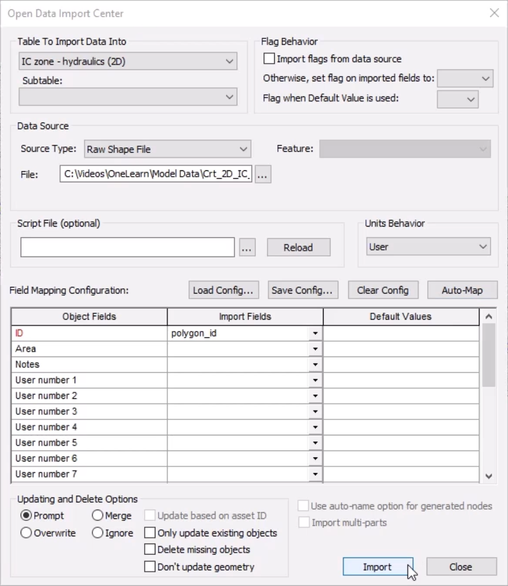
- From the Network menu, click Import > Open Data Import Centre to open the ODIC.

- In the Table To Import Data Into drop-down, select IC zone - hydraulics (2D).
- Under Data Source, ensure that the Source Type is set to Raw Shape File.
- Click the More (…) button.
- Navigate to and select the .shp file—in this example, IC zone – hydraulics (2D).shp.
- Click Open.
- Under Field Mapping Configuration, click Auto-Map to search the import file for fields that match.
- Click Import.
- Click OK to close the notification.
- Close the ODIC.
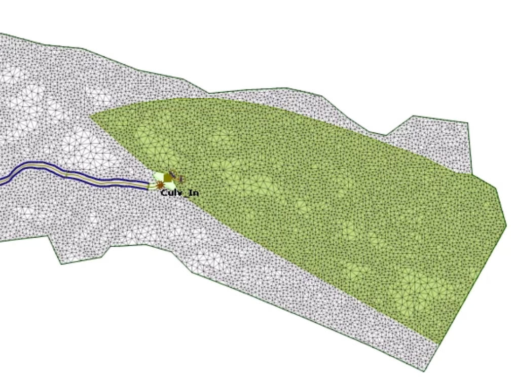
The IC zone is imported into the model as a polygon covering the area where the initial conditions will be applied.
Now, the initial condition objects must be created. For this example, they are imported from existing files.
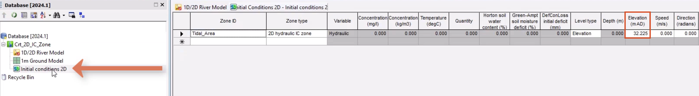
- In the Database, right-click the Model Group, and select Import InfoWorks > Initial conditions 2D > from InfoWorks format CSV file.
- Navigate to and select the .csv file—in this example, Initial conditions 2D.csv.
- Click Open.
This applies a level of 32.255 mAD to the Tidal_Area IC zone.
- From the Database, double-click the object to inspect the content.
Next, apply a level file at the boundary line of the IC zone to set the tide level during a simulation:
- From the GeoPlan Tools toolbar, expand the New Object Type drop-down and select Line.
- Click New Object.
- At the downstream extent of the IC zone, add a line, making sure that the line is collinear with the boundary of the IC zone.
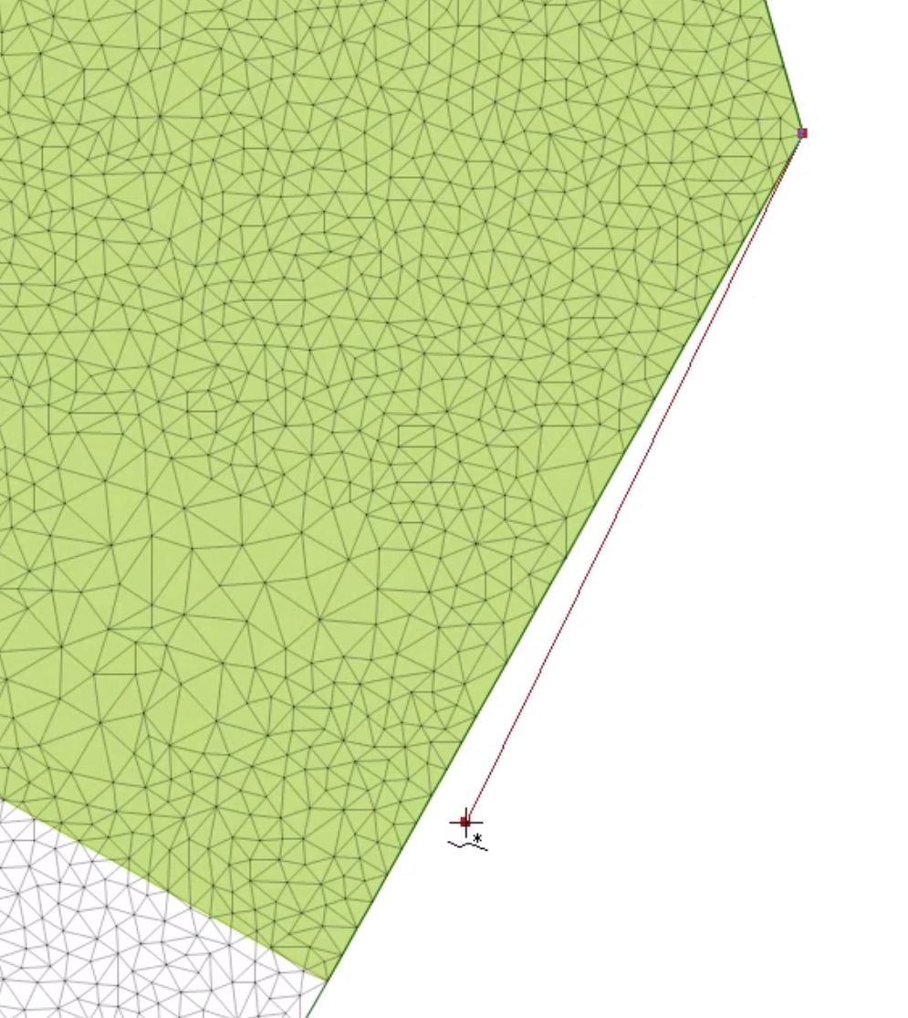
- Double-click to close the line.
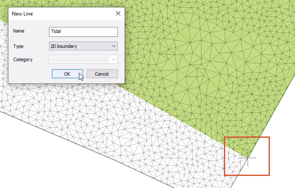
- In the New Line popup, add a Name of “Tidal”.
- Set the Type to 2D boundary.
- Click OK.
- In the 2D boundary Properties window, set the Boundary line type to Level.
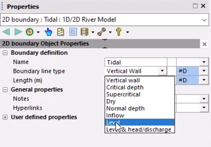
This allows the level at the boundary to be set via a Level Event.
Regenerate the mesh so that these additional objects are included:
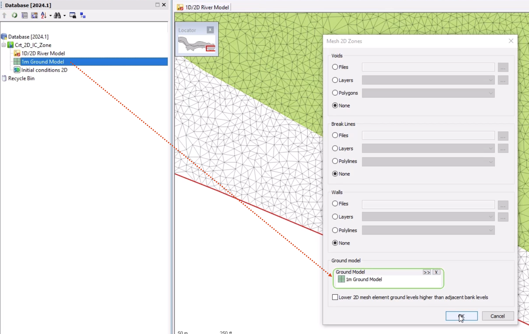
- With the 2D zone selected on the GeoPlan, select Model > Meshing > Mesh 2D zones.
- From the Database, drag the 1m Ground Model into the Mesh 2D Zones dialog box and drop it into the Ground Model group box.
- Click OK.
- In the Schedule Job(s) dialog box, click OK.
- Once the mesh has completed, from the Job control window, click the Mesh ready status.
- In the Manage mesh results window, click Load mesh.
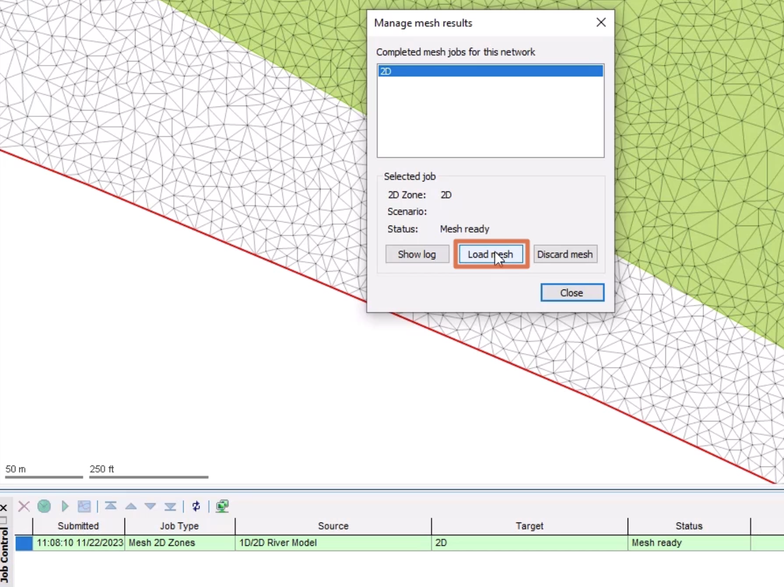
- Click Close.
- Click Validate to make sure there are no errors in the network.
- In the Network Validation popup, click OK.
- Click Commit changes to database to save the changes.
- Add a comment, such as "Added IC Zone and 2D boundary".
- Click OK.
The 1D-2D river model is now complete and can be used for simulations.