00:03
UPC scripts allow you to represent the valves and pump stations within a water supply system
00:10
that may be controlled by a more complex set of rules with multiple conditions.
00:15
This UPC script example sets a valve control to perform a rezone exercise following a rupture of a pipe.
00:22
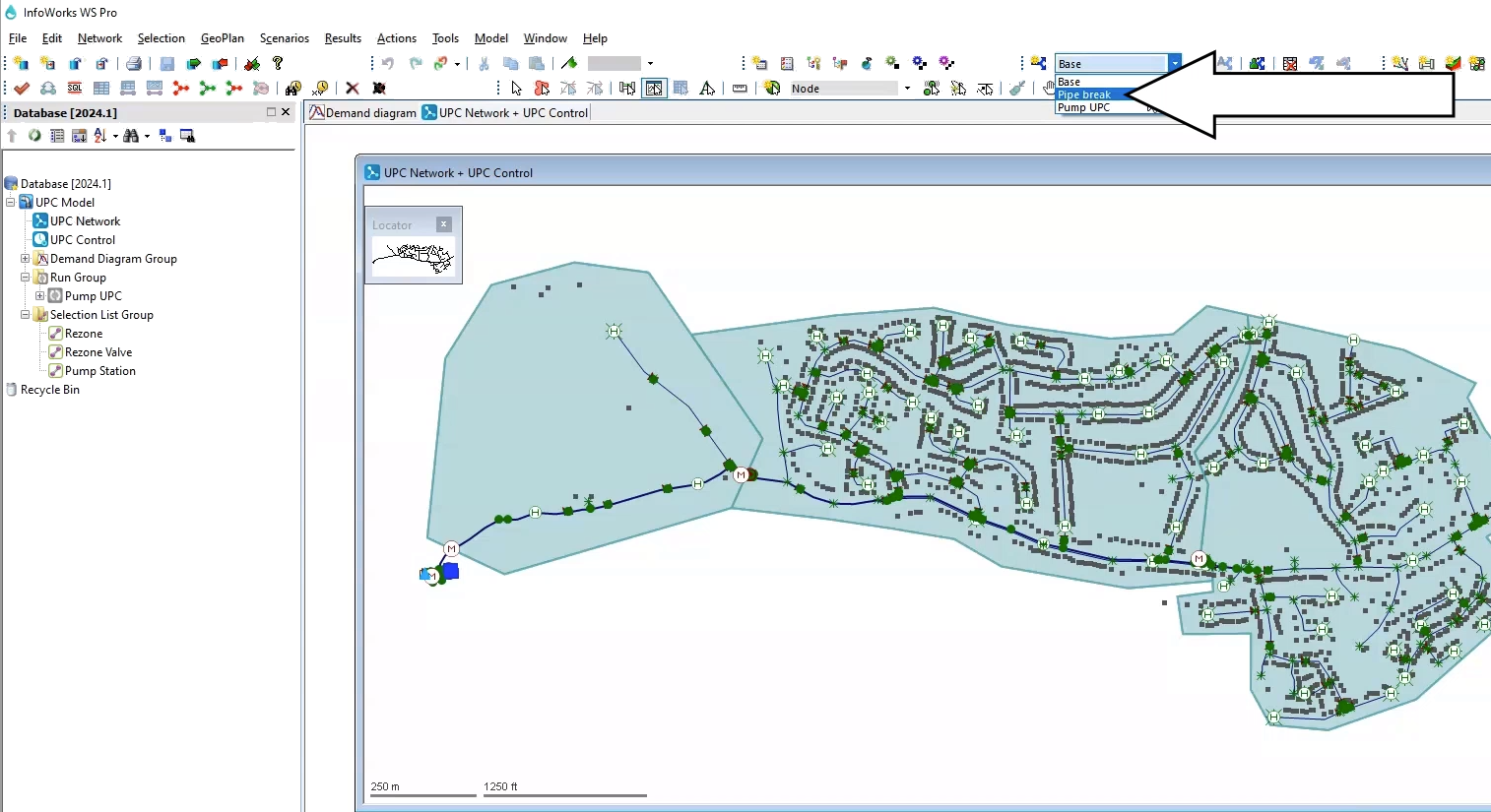
From the Model Group window, expand the UPC Model model group.
00:27
To open the UPC Network and UPC Control, double-click the UPC Network or drag and drop it onto the workspace.
00:35
In the toolbar, from the Scenario menu, select the Pipe Break scenario.
00:41
In this example, Pipe 109755 has been set to rupture between 08:00 and 12:00.
00:50
When this rupture occurs and the downstream network is left without water supply,
00:55
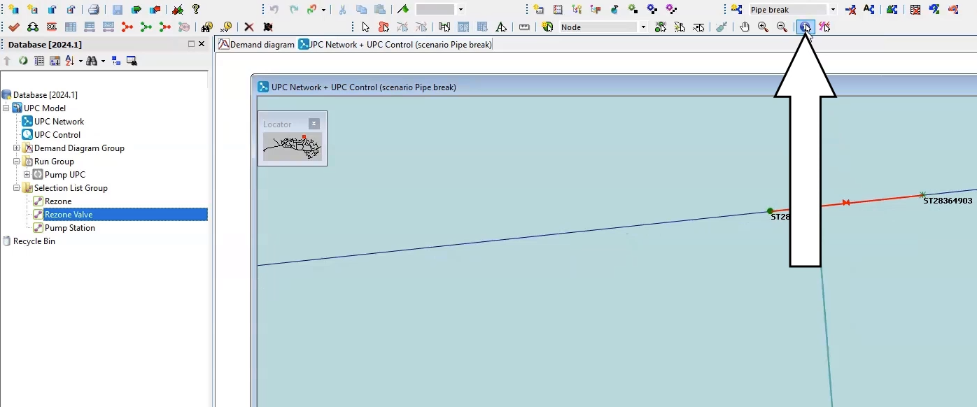
a mitigation method is to rezone the DMA using valve 234298.
01:01
Drag and drop the Rezone Valve selection list onto the Geoplan to identify Valve 234298.
01:09
Using the Properties tool, review its current control strategy.
01:13
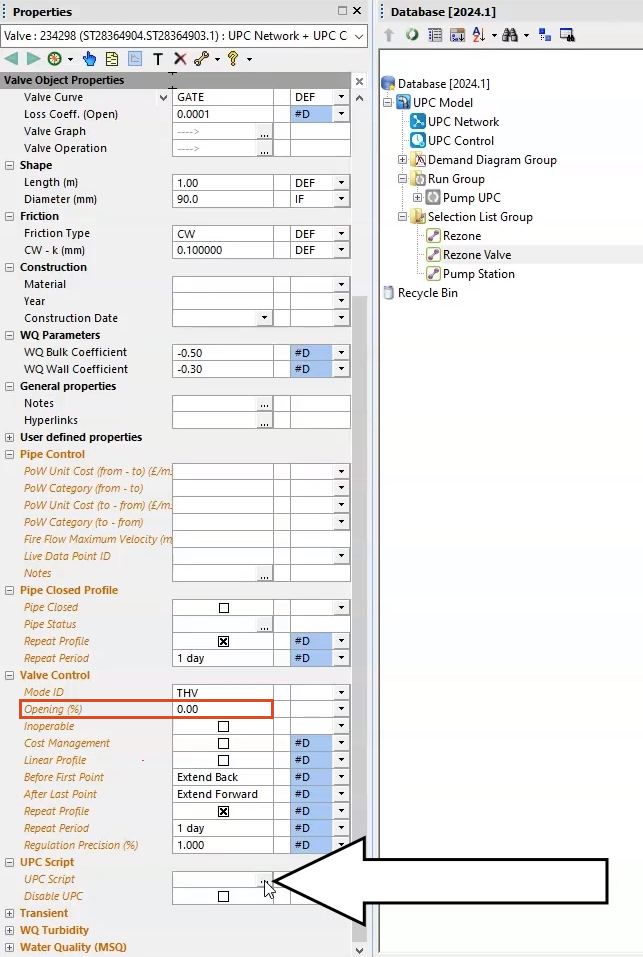
You can see from the Valve Control option that the valve is currently set to an Opening percentage of zero,
01:19
and thus the valve is closed.
01:21
You will change the behavior of this valve so that it opens when there is a supply incident in the network,
01:27
and then closes when the network behavior returns to normal.
01:31
In the Properties window of the valve, expand the UPC script menu.
01:36
In the UPC Script options, click More (…) to open the UPC Script Window.
01:42
Here, you will set the rules.
01:44
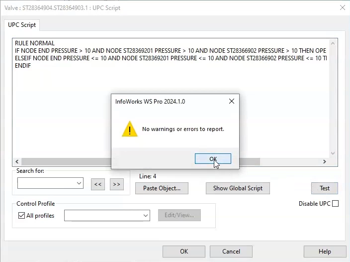
When the network is normal, the valve is closed, but when there is an incident, it opens.
01:50
From the dataset provided for this tutorial, add the lines of code provided in the Valve UPC.txt file.
01:58
Once you have populated the code, click Test to check if there are any errors or syntax errors.
02:05
When the warning message reads, “No warnings or errors to report,” click OK to close the warning message,
02:11
and OK again to close the UPC Script window.
02:15
Commit all the changes to the database.
02:19
Now, you can run the Pipe break scenario.
02:23
Right-click the Run Group, then select New > Run.
02:28
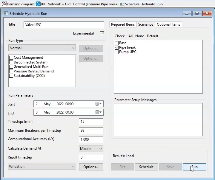
In the Schedule Hydraulic Run dialog, enter “Valve UPC” in the Title field, and check the box next to Experimental,
02:35
and then click and drag the UPC Network from the Model Group window into the Network group box.
02:41
Now, click the Scenarios tab.
02:43
Deselect the Base scenario, and then enable the Pipe Break scenario.
02:48
Then, click Save and Run.
02:52
To view the results, first click and drag the Base simulation into an empty part of the workspace window to view the results in the GeoPlan.
03:00
Now, drag and drop the Rezone selection list onto the Geoplan.
03:05
You will see the Pressure control point and the valve are selected.
03:09
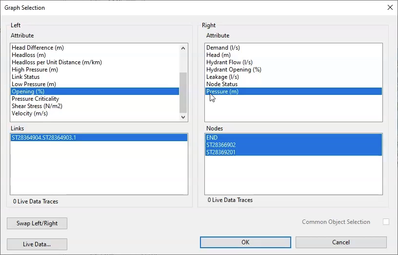
In the Results toolbar, select Graph Selected Objects.
03:14
In the Graph Selection dialog, from the Left group box, select Opening (%) and from the Right, select Pressure (m).
03:24
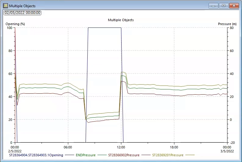
In the resulting graph, you can see that, as the pressure drops at the control points,
03:29
the rezone valve opens to allow water to bypass the rupture.
03:32
Once the pipe is mended and the flow is restored, the rezone valve closes.